I recently uploaded this sound comparison between 1st and 2nd run Rapido 44-tonners… Spoiler Alert: Now just as good as Scale Sound Systems’ drop-in replacement (but SSS’ cab filler speaker is still by far the best given its gargantuan size, if you’re willing to sacrifice the 44t’s gorgeous interior).

Showing posts with label DCC. Show all posts
Showing posts with label DCC. Show all posts
Tuesday, October 28, 2025

Monday, June 24, 2024
New Haven DEY-3 (Proto 2000 S-1) DCC/Sound GAMECHANGER!
One of the coolest (and, as in this case, mildly irritating - but in a good way :^) things about having a blog is the feedback and questions you get. It's even better when the blog reaches such a wide-ranging audience.
Like a guy in Australia(!)
Earlier today, friend RodD from Way Down Under asked me a simple question about what Scale Sound Systems speaker I used in my Proto 2000 Alco S-1 (which I converted to New Haven RR DEY-3 #0967 - click here for that build thread). I didn't remember offhand, and I was shocked and annoyed to discover that I didn't mention it in my conversion posts (here and here). Spoiler Alert: It's Scale Sound Systems part# LLPR-S1S3-RC1.
BUT!!
When I went to the Scale Systems page to find the part# for that speaker, I discovered "something new had been added..."
Apparently, since I converted my loco to DCC and sound - using a LokSound v5 micro and separate Power Pack (which I had to solder to the decoder) . . .

. . . Scale Sound Systems has produced a shorter speaker that will allow you to use the LokSound 58921 Direct w/PowerPacks built in(!)
 |
| Snipped from the Scale Sound Systems website |
You can find this speaker on the same page, but it's part number LLPR-S13S-RC1. Beware how close the part numbers are to each other.
This is a MUCH easier and more elegant solution for DCC/Sound in the P2k Alco S-1 - provided
- the "drop in" board actually drops in (SSS recommends mounting it with double-sided tape) - click here for a drop in "fail" with this board; and
- you don't actually enjoy soldering 3 tiny 30 gauge wires from a PowerPack to the decoder PC board - and trying to find someplace to stuff the PowerPack under the hood. . .

If I'd known about this new SSS speaker, I would have most definitely used it and the 58921 decoder with built-in PowerPacks instead.
But isn't that the way it ALWAYS goes?? You scratchbuild a long-coveted model, and - just as soon as you finish it - a manufacturer offers it? You build a scene with your best guess as to the look of a certain structure you have no photos of, and as soon as you're done, somebody shows you a photo of the structure - and it's totally different?
Well, chalk this up as another example of this weird "rule" in model railroading.
If you've been considering converting a Proto 2000 Alco S-1/3 to DCC & sound, hopefully I've warned you in time! :^) Just don't forget to isolate that motor . . .
Thursday, December 7, 2023
The Atlas Classic RS-3 and the ESU "Drop In" Decoder (#58921) - A Cautionary Tale
I was excited to finally get started on my New Haven DERS-2c #529 project - click here for why and what all I got in preparation.
Unfortunately, I've run into a major roadblock: The ESU "Drop In" decoder, with integrated Power Packs (#58921) does not actually "drop in" to the Atlas Classic RS-3 model I wanted to convert. In fact, it doesn't fit at all as designed.
Read on to see why - and hopefully to avoid the same (major) mistake I made . . .
 |
| ESU photo |
ESU's Loksound 5 DCC Direct with Integrated Power Pack decoder (#58921) promises a relatively easy DCC conversion, with the bonus of having "keep alive" capacitors already installed on the motherboard. While not a true "drop in" that doesn't require soldering (like the version without the capacitors (#58821)), both decoders are touted as an "easy" board replacement. I can't speak to the 58821, but I know that's not the case with the 58921 - at least not in an Atlas Classic RS-3.
 |
| When you try to attach the board to the loco as indicated, you discover that the slots are a little too close together to allow an easy install. Note the slot on the left. . . |
 |
| The spacing between the slots is a good 16th to 3/32" too short. |

But the board is supposed to fit, right? Maybe I'm being too picky?
Thinking so, I decided to press a little harder . . .
 |
| That was a mistake . . . |
 |
| A BIG mistake! |
Note that the leg of the capacitor didn't break at the solder joint - it actually pulled the solder pad up with it(!!)
UGH.
Fortunately, I hadn't gone through the trouble of soldering all the wires to the board (which the 58821 doesn't require. Just sayin'). Unfortunately, I didn't check with anybody about alternative mounting suggestions or pro tips for using the 58921 before attempting to install it.
Which is where I hope this post is helpful - not only to warn you about this board if you're trying to install it in an Atlas Classic RS-3 (I know many of you have them), but also to avoid the mistake I made - and to pass along an installation pro tip. At least it's how I plan to proceed . . .
First though, this board is on its way back to ESU. To their GREAT credit, after hearing my story they've agreed to consider replacing it under warranty. I'll let you know how that works out.
Regardless, since I really want the capacitors, I've since gathered a lot of input on how others have installed this particular board and the consensus is that they snip off at least one of the mounting clips (preferably the one closest to the capacitor) and use double-sided tape to attach that end of the board. I'll probably also use some Kapton tape to hold it all down.
So the conversion of this Atlas model into NHRR DERS-2c #529 is sidelined for the time being. But hopefully, it'll only be a temporary setback and I'll be able to continue the install soon. Fingers crossed!
PS: If any of you reading this have actually installed the 58921, please let me know. I'd really be interested in learning how you did it.
Wednesday, December 6, 2023


Friday, December 1, 2023
Friday Fun: And Now For Something Completely Different . . . (NH #529)
 |
| Outside the Essex shop, before the Locomotive Service Facility was built, c. 1986/1987. |
I first met New Haven Railroad DERS-2c (Alco RS-3) #529 in November of 1986. I was 17 years old, had had my license for almost 2 years, and was able to go on a solo railfan trip to the Valley Railroad's Railfan Day, which I'd just heard about a few weeks before.
Fast forward a few months, and I'm working on the VRR as a steam locomotive fireman and one of my "featherbedding" jobs (a hopefully good-natured accusation) then was to hold down the left-hand seat on the 529 whenever #97 (our venerable 2-8-0 and the only steamer in service at the time) was sidelined for a boiler wash. I even got to run it on a train a few times (under the watchful eye of the engineer, of course).
I was at the Valley for 3 years before college, then lawschool, then marriage and starting my career got in the way. Eventually, we bought our first house and I finally had some space for a layout. The layout I started with was a donation (read more of that story here) which didn't run all that well and was only going to represent the Shepaug Branch off of the Berkshire Line-themed layout I was planning.

Unfortunately/fortunately, the engine was DC-only (we're talking probably about 2001/2002 at this point) and I converted to DCC in May of 2003, so the 529 was sidelined until I could get around to converting it. But then I took up bike racing in 2005 and the hobby took a back seat for about half a dozen years . . .
Now that The Valley Local has been up and running well for about 10 years now, I decided to start going through my stash of equipment to see what's now surplus and can be liquidated to fund other railroad-related projects. Consequently, I've sold off 4 of 6 DL-109s that have just been sitting new-in-the-box for years (incidentally, I have 2 left to sell if anyone's interested), and then I came across this now-old Atlas Classic #529, sitting like new in the box. . .
I'd seen a while ago that Loksound had come out with a v5 decoder that has PowerPacks onboard, and is a drop in for the Atlas Classic RS-3. And Scale Sound Systems sells outstanding speakers, which are also custom fit. So suffice it to say, I took some of the DL-109 money and made a visit to the SSS website.

And the package finally showed up today . . .

So, just as soon as I can end this post, take out my contacts, and heat up the soldering iron, I'm gonna spend a lovely evening listening to the Charlie Brown Christmas album, sipping a nice Cabernet, and converting my HO scale #529 for use on the Valley Local!
 |
| "Photo Freight" southbound through "the Meadow" just north of Essex station on the Valley Line, Railfan Day, November, 1986. |
And don't bother telling me it's past my era - I've actually run the prototype locomotive over the line that I model, so there's no way I'm not going to run the model on my layout. Now I just have to see if I can get my friend Bernard to 3D scan me in a diesel engineer's pose . . .
<><><><><><><><><><><><>
The actual, real 529 still exists today, but it needs your help. The Railroad Museum of New England is in the process of restoring it to operation, but unfortunately such efforts are costly. Check out their efforts here and consider helping get the 529 running again!
Sunday, September 24, 2023
Mystery Power Outage - A Turnout Fail
So this happened . . .
I recently discovered while running my DERS-1b across this turnout that it would stall every time. After checking the wheels and rails for dirt, I used my "poor man's continuity tester" (a bulb & two alligator clips) to check that all rails were getting power.
Strangely, as you can see from the video above, one of the outside/stock rails was NOT getting power - at least not all the time. That's not too strange - I figured I might have to add a feeder to that rail - but what was really strange is that, as I would run the clip down the rail, it would get power and lose power. And it's all one solid piece of rail!
Thankfully, I was on the Wednesday Night AML Chat and showed the folks there (literally from all around the world) what was going on and I think it was Mark from Australia that first suspected a faulty rail joiner. Actually, BOTH rail joiners at each end of this rail weren't making solid contact - and thus not providing continuous power.
Turns out, as I would slide the clip along the rail, as I got closer to the rail joiner - and was pressing down - contact would be made.
So this is what having two rail joiners fail at the same time looks like. Who knew?
Well, I do now - and now so do you!
As a temporary fix, I tightened the rail joiners and all is well for now. But the longer term solution will be to add a feeder to this rail. And while I'm at it, I'll probably go ahead and add a feeder to the other stock rail (the closure rails already have a jumper soldered between them and the stock rails). And do the same thing for the other turnouts. . . Ugh.
I guess I should have just added feeders to the turnouts before installing them. But at least now I know what a failure looks like and can fix them as needed.
Hopefully this little writeup will help someone else out - and if you've ever had this happen, let us know in the comments!
Thursday, April 13, 2023
Proto 2000 S-1 Decoder Install/Test (Part 2)
As you may have noticed in my last post, I've made a bit of progress in Essex (fine-tuning some terraforming and tweaking a build template/footprint for the Dickinson's Witch Hazel distillery), and also Deep River (widening/moving the aisle to provide more room for the lace factory). But hopefully you also noticed at the end a couple of pictures of my latest decoder install. . .


This is going to be the main diesel power for the Valley Local: New Haven DEY-3 class (Alco S-1) #0967. I've been noodling on this install since at least late last year (click here for the last detailed post starting the project - "Part 1" of this conversion), trying to determine the best way to approach it and fit everything. But as of tonight, I can declare the install "DONE."

What we have here is an ESU v5 micro sound decoder (with hardwired Next18 plug), ESU PowerPack ("keep alive"), and a Scale Sound Systems speaker. Per the speaker installation instructions, I removed the weight from over top of the drivetrain and attached the speaker using the factory screw. Prior to all of this though, I first had to isolate the motor to make the model truly DCC-ready (click here for how I did that).
Couple of things to note:
- The motor wires must be backwards since I matched the gray and orange wires to the decoder, but the loco ran backwards. Instead of reversing the (now-soldered and shrinktubed) wires, I just changed the direction in CV29.
- If I were to do this install again, I would direct-wire the gray motor wire and the two speaker wires to save 3 splices (and the associated shrink tubes, and extra wire that has to be tape tucked).
- I don't think removing the 1.5oz of weight is going to make that much of a difference to me. All of my layout is flat except for a 2% grade from East Haddam to Middletown. But even on the prototype, typical trains up the grade would only be 3-5 cars max. I'll report back.
- While JT at SSS strongly cautions against any modification of his speaker enclosures, I found that I had to file down the molding ridges on both sides to allow the body/frame to slide down onto the chassis more easily. As long as you're ONLY removing the ridge, and not thinning the wall of the enclosure, you'll be fine.
- Note that I have not (yet) installed lights. I don't know that I'll bother (the New Haven didn't use headlights during the day during my era, and the Valley Local didn't operate at night), but I left the white/yellow/blue wires intact just in case I change my mind later.
- Speaking of wires, I removed/cut off the green and violet wires (AUX 1 & AUX 2, respectively) since I didn't need them, don't expect to ever need them, and didn't want them in the way.
- The only thing I mounted into the body shell was the PowerPack:

As you can see, it fits really nicely above the rear truck and doesn't come into the cab (which will have a full interior).
So, how does it run and sound? GREAT! And even without doing the ESU tuning. Check out the video:
So there you have it - lemme know what you think. And special thanks to the AML Wednesday Night Chat guys for keeping me company and for all the helpful tips and tricks. Those zoom chats are ideal for working at the bench - and with folks "joining" you for a visit!
Next step(s): Modifying and detailing the body to transform this model into as true a representation of a DEY-3 as I can. Stay tuned!
Wednesday, April 12, 2023




Sunday, February 19, 2023
Quick Progress Update
After all the flurry over the past couple of months working on/finishing the SW1, then trying to get as much done as possible on the layout - culminating in a big op session and Springfield Weekend, the Valley Line took a back seat for a while as I tried to catch up on everything else I'd been able to let slide in the meantime.
But like crocuses poking up through the snow, the Valley Line has started to wriggle back to life a bit. Here's a quick sampling of what I've been up to lately on the layout. . .
 |
| After vacillating for, literally, years and having them languish on my Christmas lists, I finally purchased the rest of the throttle holders I needed. They've obviously never been a high priority - my operators have never complained there's no place to put the throttle (probably cuz they're usually 2-man crews), but I noticed their absence every time I operated the layout solo. And now that I'm getting more scenery done, I'm less and less willing to lay the throttle on the layout. |
 |
| I also found this PSX-AR (combo circuit breaker/auto reversing unit). Long time readers may remember the troubles I had with shorting at the ends of the reversing section between Middletown and Wethersfield (click here for the background). Well, way back in Sept. 2021, I'd borrowed a PSX-AR which seemed to fix the problem. So I purchased one of my own, but then was able to get my old PSX-AR units working. So the new unit sat in a box. That is until recently when the old unit decided to start acting up. Out came the new unit, on went a piezo speaker, and here it is semi-permanently installed on the layout. I want to get a bunch of op sessions into it before I mount it more permanently, but so far so good . . . |
 |
| Speaking of op sessions, I noticed that my radios were starting to show evidence of, um, being dropped. I know at least one of them got totally trashed when *I* dropped it, but it's a bit of a mystery how the others have fared so poorly. No worries though - I've been wanting to upgrade them for a while anyway and now I had an excuse, and found a 4-pack on sale! |
 |
| Even better, these come with headsets which I'd been wanting for a while (and which may reduce the amount of handling and the risk of droppage). Also, these are rechargeable (no more blowing through packages of AA batteries). I'd initially just plugged all the chargers into a power strip on the floor. But FB friend Ces Ses suggested a more elegant solution. I love building things, so I created the nice shelf and cord routing you see in the pics above. Looking forward to the next session to try them out! |
 |
| As for actual layout progress, there's a bit o' activity happening down at Saybrook Junction. DickO was over recently to remove some of the fascia to accommodate a plexiglass barrier which will eventually protect the end of the Route 1 overpass he's building for the east end of the Saybrook Scene. Looks like I'm going to have to finally bite the bullet and decide on a ballast for the track in this area... |
 |
| Before track can be ballasted though, it needs first to be painted and weathered. Fortunately, the track in Saybrook already has a base coat, but the track between Essex and Deep River doesn't. Well, it didn't. And since I'm hoping to get some tie weathering done in Essex tomorrow, I figured it'd be a good idea to continue the base coat from Essex "north" around the end of the peninsula. I used to swear by using Krylon camo paint for the base coat ("Earth Brown"), but during the winter especially - when you can't open a window or put a fan in - the rattlecan fumes are especially noxious, if not downright dangerous. Thankfully, RalphR suggested I leverage my new-found enthusiasm for the airbrush and use it to paint my track with an IPA-based acrylic rather than a rattlecan lacquer. The setup is pictured above: portable compressor, hose with in-line moisture trap, Patriot 105 'brush, stand, and Tamiya Linoleum Deck Brown paint, thinned 1:1 with 90% IPA. From setup to cleanup took about 40 minutes and no (or at least fewer) brain cells killed. |
 |
| The weathering step is even safer since I just drybrush water-based craft paints onto the ties. The paints I use are above (and staged for work tomorrow), and the technique I use is outlined here (just scroll down a bit). |
Oh! One last thing I did was to finally finish affixing the track in Middletown yard . . .

The yard has been in the same configuration - and operated successfully - for probably close to 10 years now. And the only thing I've changed at all is the length of one of the stub-end sidings. So, since I now have a winter/indoor friendly track painting technique, I figure I'll soon be painting & weathering the tracks here, in preparation for scenicking the yard itself. But before all that, I had to install some filler ties and glue down the track.
Typically, this would entail my laying a bead of white glue down the side of the track, lifting the track up, then pushing the glue underneath the track with a business card or putty knife. But Boomer Diorama (via the Mudfather) suggests dribbling Matte Medium down the center of the track, letting it wick underneath the ties to fix it in place. It'll dry dead flat and, best of all, no need to move or disturb the track at all.
So I tried that - I'll let you know how it worked out.
So that's where things currently stand. JimD is visiting tomorrow to help with some more scenery, so hopefully I'll have even more layout progress to share soon!
Wednesday, June 22, 2022
Programming a LokSound v5 Decoder for the ProtoThrottle

Ever since I decided to add an EMD SW-1 to the Valley Line (incongruously, as it happens), I knew I'd want to dial it in for the ProtoThrottle. If you're not familiar with the ProtoThrottle, be sure to click here. I also programmed and configured the throttle to work with the function mapping I use on my decoders. For more on how I did that, click here.

Note that my function map likely differs from yours, and certainly isn't the default mapping, but I starting setting up my ESU decoders this way so that the status of Drive Hold (mapped to F5) and the Brake (mapped to F6) would show up on the screen of my NCE dogbone throttle (which only indicates the status of F1 through F6). The other anomaly you may notice is that I have 4 (four!) separate functions for my headlights - Front & Rear, Bright & Dim. This allows me to take advantage of the light switches on the ProtoThrottle.
I've programmed ESU/LokSound Select & v4 decoders for the ProtoThrottle before (click here for an overview of how I did it), but after hearing the v5 in my New Haven DEY-7 (SW-1200), I knew I had to install one in the SW-1. Unfortunately, I couldn't just load my Select/v4 programming into a v5 decoder, so I had to relearn how to do it. And I wrote down all the steps so I could refer back to this in the future. Maybe it'll help you too . . .
First step & best tip: Get a LokProgrammer - or at least download the free software. Even without the hardware, you can do everything I describe here using the software to get a report of the CVs that need to be changed. You can also save the .esux file so that it can be loaded into your engine by someone that has the hardware.
While my description below refers to the specific tabs in the LokProgrammer software, you should be able to use DecoderPRO to do this programming as well. But I haven't tried that, so YMMV.
To keep things brief, I'll just tell you what I changed - if I don't mention it, I left it at its default setting.
So, without further ado (and with special thanks again to Pete Mulvany who first helped me through all this), we'll start with the Address tab...
Address
Select the "Use Long Address" radio button and input your engine number
Analog Settings
Uncheck the "Enable DC analog mode" box
Brake Settings
This is where the v5 differs significantly from the Select/v4 decoders. You have a number of sophisticated brakes available. I only use the independent brake (Brake1). Under "Brake Functions," I made the following changes:
- CV179 from 128 to 237 (adjusts time it takes to stop; adjust to taste)
- CV182 from 126 to 0
- CV180 from 128 to 0
- CV183 from 126 to 0
- CV181 from 240 to 0
- CV184 from 126 to 0
DCC Settings
- Disable RailComm (if you don't have Lenz, etc - I use NCE)
- Confirm 28/128 speed steps
Driving Characteristics
- I set CV3 to 30. This CV controls the time it takes to move between notches, so adjust to taste. A value at the lower end of the range makes the engine more responsive - perfect for a switcher.
- Set CV4 to 255 (maximum momentum - this way you have to use the brake)
- CV24.6:0=127
- Uncheck starting delay
Function Outputs
I went to this tab next to create 2 new lighting functions - Headlight Dim & Rear Light Dim - and adjust the existing lights to make the transitions between dim and bright more realistic.
- Front Light [1] (this is the headlight on bright)
- Changed from "Dimmable" to "Ventilator"
- Changed Acceleration Rate from 16 to 2
- Changed Deceleration Rate from 0 to 1
- Front Light [2] (this is the headlight on dim)
- Changed brightness from 31 to 3 (adjust to taste)
- Check LED mode
- Confirm "Dimmable Headlight, Fade In/Fade Out"
Repeat this process for the rear light.
Function Mapping
This is where you'll 1) remove the directional lights and reconfigure them to work independently on the ProtoThrottle, and 2) remap functions to match your standard. The process isn't complicated, but it's too much to describe, so I'll let this picture do the work of 1,000 words (hopefully it's worth that much):

You'll definitely want to click on this image to enlarge it. It shows all the changes I made to match my preferred function mapping. I only modified up to F9, and I set F11 to air compressor. I left everything else at the default settings. Depending on how/where you like your functions, this step may take a while. The main change you'll need to make is to remove the directional headlights and divide them up into 4 separate functions. And - most importantly - make sure that the functions in your decoder match the function settings on your ProtoThrottle and vice versa.
(At this point, I saved a copy of the file as a "v5 Master File" so that I could just load it into future v5 decoders, saving me all this manual labor. Then all that's left to do is customize the motor and sound settings - and that typically varies from loco to loco and speaker to speaker.)
Motor Settings
This will vary according to your taste and the capability of your particular locomotive. But here's what I did:
- Enabled motor overload protection
- Used 3 point speed curve with the following settings (remember this is a switcher):
- CV2=2
- CV6=37
- CV5=75
Special Options
Check both memory settings
After that, you'll likely want to play around with the sound settings & volumes, as well as explore the different horns, bells, etc. - but beware of the possible rabbit holes!
And since you probably have a ProtoThrottle (or else you probably wouldn't bother reading this far - if at all), you'll certainly want to configure the notching to match what's in the decoder. The ProtoThrottle website has an excellent How-To article on that here. And while I only briefly covered changing the headlight functions, this article goes into it in more detail.
Speaking of more detail, as you can imagine I've only scratched the surface here since these are really just notes for my future reference. But hopefully it'll provide you with a quick overview of what's involved. If you have any questions, I'll help if I can - or will at least try to get you to someone that can help us both (paging Mr. Mulvany . . .)
And if you have any suggestions on how to do things differently (especially with regard to all those different brakes!), or what works best for you, be sure to let us know in the comments!
Friday, April 22, 2022
DEY-5 #0604 - PowerPack & Cab
It's been pretty busy 'round here, but unfortunately because of the day job rather than the layout. But you didn't come here to hear about that - we all have #adulting challenges that get in the way from time to time. So given that your time is likely as limited as mine these days, I'll get right to it . . .
The Atlas S-2 comes with an OEM Loksound Select decoder. It runs great as-is, but I've discovered that adding a "keep alive" capacitor provides some nice peace of mind that the sound is never going to cut out nor is the engine going to do any herky-jerky and ruin the effect we're after on our railroads.
Fortunately, installing the ESU version of the "keep alive" (called a "PowerPack") is relatively straightforward. You only have to get over your fear of soldering - on really tiny soldering pads...
The first thing you do is remove the decoder from the motherboard. Just carefully wiggle/pry it off.
MY biggest challenge was actually being absolutely certain I was soldering to the right pads. The instructions help . . .


Next, plug the decoder back into the motherboard - and try to figure out where to fit the PowerPack(!)
Truth be told, I did do some test fitting ahead of time to make sure it would fit. It's not elegant, but there's plenty of room for it in the cab - and that meant I didn't have to try and mill out anything under the hood for space.


As you can see, I taped the sockets for the plugs from the rear light to the PowerPack to try and keep things tidy.
PRO TIP: In order to activate the PowerPack and have the decoder recognize it, you need to set AUX 6 to "Disable" (the default setting is "Dimmable Headlight"). This is easiest to do using the LokProgrammer. The AUX 6 setting is in the "Function Outputs" section. Even if you don't have the LokProgrammer hardware, the software is free and can be downloaded here. The software will show you what CVs you need to change. According to the software, changing AUX 6 to "Disable" requires you to:
CV31 = 16, CV32 = 0
----------------------
CV315 = 0
But, like I said, it's easiest to use the hardware. Or have a buddy do it for you :^)
Ok, that's enough electronics. Back to modeling!
After LOTS of vacillating, hemming, and hawing about how to assemble the cab, it basically came down to just doing it. I was happy to discover that the edges of the walls had perfect 45 degree bevels so I applied some slow-setting thick CA to an edge and then used my 1-2-3 blocks (which have perfect 90 degree corners) to hold the walls in position while the glue set. I did the back to a side and the front to the other side. Then I glued these two subassemblies together. Before the glue totally set, I added the roof, making sure everything was square and that the tops of the four walls met the locating ridges on the roof properly.


This was all made a bit more stressful by the fact that everything was painted and decaled already. And you can see in the top photo that there's a small gap between the top of the wall and the cab roof. I think next time I'll assemble the cab first so any additional body work can be done before painting.

The handrails ended up being more complicated than I expected. I realize now that I should have mentioned that I applied the long rails on each side of the doorway - and the little grab iron to the left of the light - before I painted the back wall. Fortunately, those details are easy to locate - Mike has molded the NBW detail right where you need to drill the holes and you can use the little grab iron from the Atlas parts for the grab next to the light. Unfortunately, you'll have to bend the door railings to fit.
The stair rails were what was complicated. But fortunately, I came up with a solution:


And another . . .

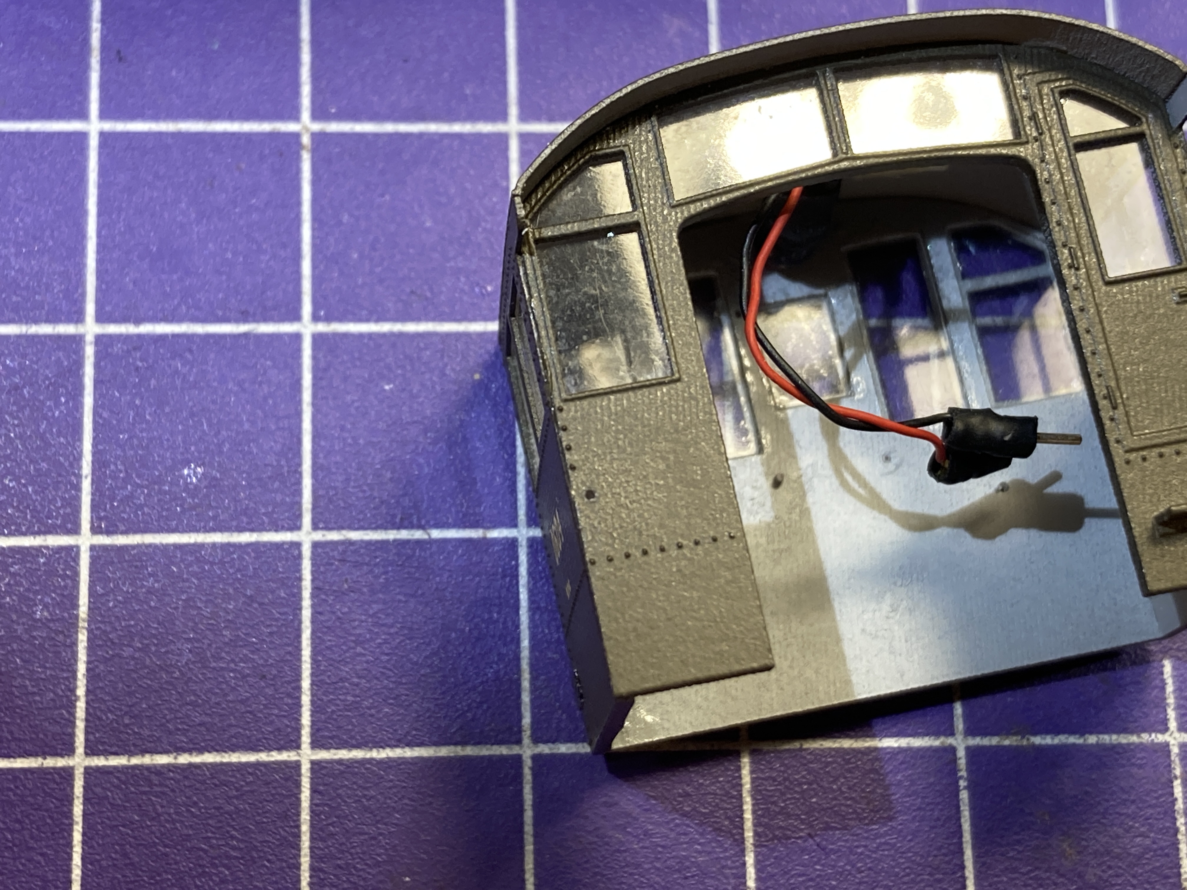
You can just make it out below the window on the left (engineer's) side of the cab.
It was when I was fitting the cab to the frame that I discovered that the cab wouldn't stay down - the PowerPack and light wires kept pushing it up off the frame.
And then I discovered why . . . Unlike the Atlas cab, there were no locking tabs in the resin-printed cab. So I made them.
Here's a shot of the slots that the stock cab locks into:


Then I glued some strip styrene to the insides of the walls to make the locking tabs . . .


A little bit of styrene here goes a long way - and you only want JUST ENOUGH to keep the cab in place - not so much you can't get the cab off once it's locked in.

And you'll want to be sure and sand a bevel in order to make it easier to slide the cab onto the frame. This all took a bit of trial and error and test fitting to get that perfect match of positive lock along with ease of removal.
With the cab done, it's REALLY starting to look like a New Haven DEY-5, rather than just another Alco S-2. We're in the home stretch now, with a little scratchbuilding and adding some additional details being all that's left to do. But these details will go a long way to "New Havenizing" this model - so stay tuned!
Subscribe to:
Posts (Atom)