

Wednesday, November 30, 2016
Tuesday, November 29, 2016
Quick Tuesday Tip: ID'ing Photos
Like a lot of you, I'd wager, things are pretty busy what with the holidays and all. But I came across a really interesting blog post that gives you 3 great tips for being a "detective" in identifying historic photos. There's nothing here having anything to do with the Valley Line, but I think you'll find the info really helpful - I know I did!
Check it out by clicking here or at:
https://forgottennewengland.com/2016/11/23/3-quick-tips-to-unlock-the-secrets-of-an-old-lowell-photo/
Check it out by clicking here or at:
https://forgottennewengland.com/2016/11/23/3-quick-tips-to-unlock-the-secrets-of-an-old-lowell-photo/
Sunday, November 27, 2016
More Christmas Module Progress
What could be more fun to work on during the Thanksgiving Holiday than a Christmas scene, complete with railroad station, church, Christmas tree salesman and a little town, complete with gazebo and town Christmas tree? For a taste of what I mean, check out my last post. That was the former layout that had to be scrapped. But I'm salvaging all that stuff for this new module.
I started with rudimentary benchwork - just a simple open-grid, with a masonite top, covered with 2" foam - and then got out the buildings from the old layout to see how everything would fit. I even built an overpass to carry the main road over the tracks. That's where I left off last weekend.
With some available time around Thanksgiving, I decided to continue progress using foam for scenic forms. My first experience with using foam this way was last Christmas - and it didn't go well, not at first. But being a little older and wiser, I gave it another go and things moved so fast that I was already well along before I took the next progress photo, showing an overview with the bridge temporarily in place and the town roughly laid out...

Since pictures are worth a thousand words - and you'd probably rather see photos than read a lot of text - I'll let them bear the burden of showing my progress over the last few days. I'll chime in in the captions as needed.
Once the plaster cloth was draped all over the forms, smoothing out all the rough edges, I mixed up a batch of "snow goop" - which is basically ground goop, but without the brown paint. Unlike my first Christmas layout where I used Sculptamold, I decided this time to try Celluclay as the base, Mix that with white glue, white latex paint, and enough water for a peanut-butter-like consistency. Spread like you're icing a cake.

And here's where things stand as of this evening. The plaster cloth had "violated" the water surface a bit, so I spread a thin layer of my goop over it to smooth things out. I "drifted" goop along the road to look like it had been plowed (and had the added bonus of clearly marking the road's boundaries), and used some goop around the rock, wall, and portal castings to put them "into" the scenery.
So far so good - but I'm leery of how the Celluclay is going to work out. It seems to be MUCH more lumpy than the Sculptamold, so the surface isn't nearly as smooth as it probably should be. I tried to take a wet brush to it to smooth it out, but the lumps didn't take kindly to that. I'll see what it looks like when it dries, but I may have to do some sanding....
But all in all, I've made a LOT of progress over the past week so am on-target to having this done - if not in time for the next Photo Library get together - at least in time for Christmas!
I started with rudimentary benchwork - just a simple open-grid, with a masonite top, covered with 2" foam - and then got out the buildings from the old layout to see how everything would fit. I even built an overpass to carry the main road over the tracks. That's where I left off last weekend.
With some available time around Thanksgiving, I decided to continue progress using foam for scenic forms. My first experience with using foam this way was last Christmas - and it didn't go well, not at first. But being a little older and wiser, I gave it another go and things moved so fast that I was already well along before I took the next progress photo, showing an overview with the bridge temporarily in place and the town roughly laid out...

Since pictures are worth a thousand words - and you'd probably rather see photos than read a lot of text - I'll let them bear the burden of showing my progress over the last few days. I'll chime in in the captions as needed.
 |
| Closer view of the overpass in place. Note the pins temporarily holding things together. Foam takes me a bit longer and is more fussy than my usual cardboard strips & plaster cloth method, but it's much cleaner and gives me a LOT more control. |
 |
| Overview of the pond area with some structure outlines. I decided to use foamcore board for the road rather than try and rasp a ramp/road from layers of foam. I find it much easier to get a good, quick grade. |
 |
| Outline of the pond, section where the trestle will be, and a larger lake outline. Structures temporarily in place. |
 |
| I used a hot knife to cut out the water areas and a serrated knife to cut the roadbed. The initial plan was to have the water be right on the masonite. I used 2" foam to give me enough height - but quickly discovered that it was too thick - the water area looks more like a canyon than a nice, bucolic pond. |
 |
| The solution was to "backfill" with another layer of foam. If I had it to do over again, I would've just used thinner foam to begin with. |
Even with the "less canyon-y" look, the pond on the far side of the tracks still looked a little contrived for my taste. But, like the Grinch, I got a wonderful. awful idea.... I found an old tunnel portal in my scrap box and decided it'd make a fine underpass/culvert for a creek to feed the pond....
 |
| Here's the portal and my markings for the new edge of the pond, and where I'll be recessing the portal. You can see I already carved out the area for the creek. |
 |
| Since I didn't want folks to see bare foam inside the tunnel, I decided to line it. At first, I was going to use crumpled aluminum foil and paint it black to represent blasted rock. But this module is supposed to be a quick job, and cardboard was just as effective and easier to do. Paint, bend, and fit into slots. You can see here that I backfilled the creek bottom with more foam to be even with the level of the pond. |
 |
| Overview shot of the pond with the culvert - and wingwalls! - in place. I got the wingwalls - and the little retaining wall you see between the house and the track - out of the scrapbox. |
 |
| I didn't want the tunnel to just be a literal black hole - it's supposed to be an overpass that continues out the other side of the fill the road is built on. So I used an old mirror to "double" the length of the tunnel and brighten it up. Couple of quick points: I was able to get the round mirror cut in half for free at a local glass place; I had to angle the mirror to be parallel to the portal (otherwise, there'd be an unrealistic angle "inside" the tunnel); and I used hot glue to affix it, held in place with pins while the glue cooled. |
 |
| I think the mirror make a HUGE difference! You can see my ear "on the other side" of the road. |
 |
| I also robbed my scrap box for some old rock castings (bonus! they were already colored). Here you can see where I've marked the foam for cutting to accommodate the casting. |
After looking over the scene, I still wasn't happy with the shoreline. It was just too vertical and didn't look very realistic to my eye. The solution was to "soften" the shore a bit, even if that would make the pond area narrower. No worries though - since the "pond area" is now a creek, the narrower waterway looks fine. Here's how I did it:
 |
| I could've used more foam, carved to fit, but that would have taken too long and been too messy. So I just took some wadded-up newspapers, added them to the shoreline to make a more gradual slope, and used masking tape to hold it down. Easy! |
 |
| Another view of everything before starting the plaster cloth. |
Once the scenic contours were all done, it was time to smooth things out further with a layer of plaster cloth - especially over the newspaper & tape. That step is the messiest of the process, but goes quickly. So quickly that I didn't get any photos other than this one:
 |
| Over on the right, you see a pan of water, roll of plaster cloth, rag, and clean tub of water to clean castings if I got any plaster on them. |

And here's where things stand as of this evening. The plaster cloth had "violated" the water surface a bit, so I spread a thin layer of my goop over it to smooth things out. I "drifted" goop along the road to look like it had been plowed (and had the added bonus of clearly marking the road's boundaries), and used some goop around the rock, wall, and portal castings to put them "into" the scenery.
So far so good - but I'm leery of how the Celluclay is going to work out. It seems to be MUCH more lumpy than the Sculptamold, so the surface isn't nearly as smooth as it probably should be. I tried to take a wet brush to it to smooth it out, but the lumps didn't take kindly to that. I'll see what it looks like when it dries, but I may have to do some sanding....
But all in all, I've made a LOT of progress over the past week so am on-target to having this done - if not in time for the next Photo Library get together - at least in time for Christmas!
Wednesday, November 23, 2016
Wordful Wednesday #146 - Christmas Layout v.1
To get you in the Holiday Spirit, I'm posting some photos from my First Completed Layout Ever - structures, even scenery, done. This was a Christmas layout I built way back in the mid-1990s in our first apartment. It was only 3x4' and had an 18" radius loop of snap track. But it was finished and ran - and even had lighted buildings!
I had a lot of fun with that little freelanced fantasy layout, but with the construction of my current large proto-layout, the old Christmas layout finally got too much in the way But it will live again - reconstituted in a module/diorama that I'm currently building. And the memory of it lives still, in the photos below.
Enjoy! And may you and yours have a Very Happy Thanksgiving!


Tuesday, November 22, 2016
Working on the Christmas Layout
Sometimes a change of pace from strict prototype modeling and research can be a welcome break and give your creativity a chance to stretch its legs. I've mentioned before (here and here) that I've started a Christmas layout (or module or diorama) using items I salvaged from a my first finished layout ever (which was "Christmas Layout ver.1").
Now that the benchwork is done and the foam is firmly glued, it was time to unpack the box o'stuff.
 |
| Everything was carefully packed away after last Christmas and the layout itself taken to the dump. |

But I figured pretty early on that the "mainline" would enter & exit off the edge, rather than abruptly end at the ends. And I wanted a nice, gentle "mainline" curve, with room for a small trestle or causeway at the left end.

After a LOT of rearranging, I came up with what I think is going to work for the town. Nothing too crowded, the main street will come on-scene at the lower right and go back and all the way to the left end, with a little side street (the cardboard strip) dead-ending at the track, but providing access to the house. The main road will then go up and over the railroad at the left end of the scene.
"How" you ask? Why, on a "Rural Timber Overpass" which I just happened to have on-hand...
 |
| It's so easy & quick to put together that I was already done with the deck before I thought to take a photo. |

The only reason it took me two nights is because I wanted the deck to be really cured before manhandling it to add the trestle bents/supports. But construction went very quickly using Testors Model Masters glue:
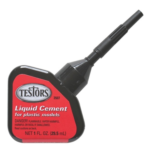
I really like this stuff - it has a higher viscosity (it's thicker) so has some gap-filling properties and a quick cure rate. The needlepoint applicator is also handy.
Best of all, since I was at the bench rather than down in the basement working on the layout, I got to put a fire in the railroad stove and have a nice cozy evening with the family. As you can see, Rosie is thoroughly enjoying herself...

Thursday, November 17, 2016
Finishing the Vinyl Valence & Christmas Module Progress
Once the paint dried on the vinyl (click here for pics of the valence construction so far), it was time to Hang the Valence! Here are some "before" shots to remind us how the Saybrook Scene looks(ed) coming down the stairs:
Not bad overall. It's certainly better to have the lights than not have them, and you don't really notice them too much while you're operating. You're concentrating more on what you're doing than on what's above your head. But best practice is to try and frame our scene - it provides a nice, finished look, especially for when you're not operating and/or when non-RR guests visit. Having a valence will make this look much nicer overall and fit better with non-RR sensibilities (it's amazing what layout owners and model railroaders are willing to accept in the service of More Layout...)
While I chose vinyl for its light weight and ease of installation, it's still a good idea to have a friend (or the Missus - well, she's a "friend" too, of course) help you out. It's a long roll of material and having a 3rd and 4th hand help hold up the roll while you staple is especially helpful.
And that's what I did. I started at one end while the Missus held up the rest of the roll. I took great care to make sure the first few staples attached the end of the vinyl all straight and square. Then it was just a matter of having more vinyl fed to me as I continued to staple the top edge to the edge of the plywood formers.
Unfortunately, I couldn't get any pics of that actual process - our hands were kinda full. Literally.
When I got to the end of the 9' run, there was of course still farther to go. So I got the other piece, started at the other end, and used the same process. When the 2nd end got close to the 1st end, I had a decision to make: butt the ends together and splice with another piece of vinyl glued to the back of the joint - or overlap them?
I chose to overlap since getting the ends/edges to match perfectly would be difficult - if not impossible for me to do. So I cut the 2nd piece back a bit so that only about 6" would overlap (I used a small T-square to help me mark a straight, perpendicular cutting line). Then I tucked that in behind the end of the first piece, applied vinyl glue, and pressed the two ends together. To keep them together while the glue set, I improvised a looooong clamp:
That was good enough to hold things together overnight while everything dried/cured.
And here are the "finished" photos! Compare to the "before" photos above since they're taken from similar angles
I REALLY like how this came out, and think you'll agree that it's a huge improvement. While most folks paint the valence black or some other dark color (based on the theater maxim paint it black to make it disappear) I think it looks better matching the wall color. And the vinyl was VERY easy to work with and cut - much easier than masonite. Not to mention orders of magnitude lighter and easier to install.
The only regret I have - and it's a small one - is that I should have made it just a little bigger/wider. At 16" everything is covered nicely from a distance - or if you're tall (over 6'). But shorter folks will still see the lights under the valence and get the glare. Not awful - and it's better than no valence at all - but I'm going to try a deeper valence in future installations - certainly 18" (which would have worked fine here) and maybe as much as 20" (as long as folks aren't bumping their heads too much on it).
In between all this, and considering Thanksgiving is only a week away, I also continued work on the Christmas module:
Nothing at all innovative here, but certainly shows how quick and easy a project this is - and ideal for the first-timer. More pics to come as I make additional progress.
 |
| Notice the shop lights, wires, HVAC piping |
 |
| Turning 45 degrees right. |
 |
| Overall shot of the Saybrook Scene |
While I chose vinyl for its light weight and ease of installation, it's still a good idea to have a friend (or the Missus - well, she's a "friend" too, of course) help you out. It's a long roll of material and having a 3rd and 4th hand help hold up the roll while you staple is especially helpful.
And that's what I did. I started at one end while the Missus held up the rest of the roll. I took great care to make sure the first few staples attached the end of the vinyl all straight and square. Then it was just a matter of having more vinyl fed to me as I continued to staple the top edge to the edge of the plywood formers.
Unfortunately, I couldn't get any pics of that actual process - our hands were kinda full. Literally.
When I got to the end of the 9' run, there was of course still farther to go. So I got the other piece, started at the other end, and used the same process. When the 2nd end got close to the 1st end, I had a decision to make: butt the ends together and splice with another piece of vinyl glued to the back of the joint - or overlap them?
I chose to overlap since getting the ends/edges to match perfectly would be difficult - if not impossible for me to do. So I cut the 2nd piece back a bit so that only about 6" would overlap (I used a small T-square to help me mark a straight, perpendicular cutting line). Then I tucked that in behind the end of the first piece, applied vinyl glue, and pressed the two ends together. To keep them together while the glue set, I improvised a looooong clamp:
 |
| "Good enough for guvmit work" as they say |
And here are the "finished" photos! Compare to the "before" photos above since they're taken from similar angles
 |
| View coming down the stairs (you can always enlarge by clicking on the image - and you can see more detail if you tip your screen) |
 |
| Overall shot of the scene. Nice! |
The only regret I have - and it's a small one - is that I should have made it just a little bigger/wider. At 16" everything is covered nicely from a distance - or if you're tall (over 6'). But shorter folks will still see the lights under the valence and get the glare. Not awful - and it's better than no valence at all - but I'm going to try a deeper valence in future installations - certainly 18" (which would have worked fine here) and maybe as much as 20" (as long as folks aren't bumping their heads too much on it).
In between all this, and considering Thanksgiving is only a week away, I also continued work on the Christmas module:
 |
| Simple 1x3 bracing for a masonite tabletop |
 |
| Loktite PL300 foam-friendly adhesive (gap on left is likely location of river/creek) |
 |
| 2" foam applied and weighed down |
Although I'm not sure when next I'll be able to get to the basement. With a fairly stressful job (especially these days), I look forward to Saturdays to recoup and (hopefully) get some layout work done and give my brain a break. But this Saturday, I'll be working on the railroad, all the liv'long day - literally. I know - weep for me :^) With my engineer training, I haven't fired in a while so I'm interested to see how I do. But I know, no matter what, getting to see the families and kids coming out to see Santa on our North Pole Express - some for the first time - will make the hours and hard work fly by. These trains sell out months in advance, but if you happen to be in Essex, CT this Saturday, come up to the steam engine and say "hi" - I should be holding down the left side of #40.
Wednesday, November 16, 2016


Tuesday, November 15, 2016
Tuesday Tip: Test Track
I've been enjoying trying to dial-in the sound decoder on my DERS-2b using ESU's Lokprogrammer, but the 3' test track I've been using hasn't given me enough run to go through all the notches on the throttle or test momentum settings. So I decided to toss the test track and build a test loop.
Bill of Materials

Next, I put together the Atlas track sections (note that it takes 16 sections to make a circle, so you'll need 3 packages of 6 to make your circle, and you'll have two sections leftover), traced the outline, removed it, and put down a bead of glue.

After spreading the glue with an old business card, I reassembled the track - including two terminal joiners I had on-hand (you could just as easily solder feeders to the track) - and weighed it down with the waterbottles while it dried.

Voila! A nice - albeit a bit large - test loop. You can see here that I've connected the Lokprogrammer to my laptop and to the track. Now I can program the decoder and make changes without having to worry about the engineflying running off the end of the track.
What's your DCC testing/programming setup look like? Let me know if you have any additional tips or suggestions you've found especially helpful.
Bill of Materials
- 2" foam board - 4'x4'
- Atlas curved snap track - 22" radius
- Terminal joiners (or solder & wire)
- Aleene's Tacky Glue
- Water bottles (with water)
I debated for a while building an 18" radius loop - it'd take up a smaller footprint (38" square, rather than 4" square) - but the minimum radius on my layout is 24" and I figured anything that could make it around 22" radius (including certain passenger cars) would do fine on my layout. 18" radius would be overkill.
Though I could certainly have cut it myself, I had the store rip cut a 4x8 sheet of 2" foam into two 4x4' sections. Made it easier to transport home too. Then I painted it on both sides with brown flat latex paint. That seals the foam, and makes it look nicer.

Next, I put together the Atlas track sections (note that it takes 16 sections to make a circle, so you'll need 3 packages of 6 to make your circle, and you'll have two sections leftover), traced the outline, removed it, and put down a bead of glue.

After spreading the glue with an old business card, I reassembled the track - including two terminal joiners I had on-hand (you could just as easily solder feeders to the track) - and weighed it down with the waterbottles while it dried.

Voila! A nice - albeit a bit large - test loop. You can see here that I've connected the Lokprogrammer to my laptop and to the track. Now I can program the decoder and make changes without having to worry about the engine
What's your DCC testing/programming setup look like? Let me know if you have any additional tips or suggestions you've found especially helpful.
Monday, November 14, 2016
Weekend Construction Update - Vinyl Valence & Christmas Layout
After my last operating session - and given how far along the Saybrook Scene has developed - it was high time to think about adding a valence to frame the scene.
The typical approach to a valence is to mount masonite above the layout in much the same way as it's used as fascia to frame below the layout. But I have a finished, drywall ceiling and - as luck would have it - my ceiling joists run the wrong way, which makes it difficult to mount anything of any real weight, It's hard to screw mounting brackets into joists/studs when you a) can't find them, or b) they aren't where you need them.
So I decided to take a different approach.
First, I traced the footprint/border of the fascia onto cardboard to create templates. I then used those templates as cutting guides to cut strips of 3/4" plywood to match the fascia curves. I used 3/4" plywood a) since it'd be easy to cut into curves (it's hard to curve 1x3s), and b) the 3/4" thickness would provide a convenient surface to which I could staple the vinyl.
The pictures tell (most of the rest of) the story. . .
That's where things are now until I can get the Missus to help me with the actual mounting. That should be MUCH easier than mounting much-heavier masonite, but still awkward enough to make an extra set of hands pretty helpful.
So while I was literally waiting for the paint to dry, I decided to start a little Christmas module/diorama/display to put at the top of the stairs outside the Photo Library room.
You may recall I have/had a Christmas Layout at one point. Click here for a photo. It was 3'x4' and represented my first actual completed layout - scenery, buildings and everything! Didn't matter it was only a loop of track - it gave me a lot of joy.
But it was awkward and bulky and always seemed to be in the way. I put it on rollers at one point so I could wheel it around as needed. But it was too wide to get through a standard doorway without tipping on its side (after removing the legs), so it was trapped in one of the basement rooms. Not great for display.
So a few months ago, I dismantled it - regaining the space permanently - and decided to reconstitute it on a display that could be out for more folks to enjoy. It'll be a fun little project - just hope I can get it done in time for Christmas!
All in all, a pretty productive weekend!
The typical approach to a valence is to mount masonite above the layout in much the same way as it's used as fascia to frame below the layout. But I have a finished, drywall ceiling and - as luck would have it - my ceiling joists run the wrong way, which makes it difficult to mount anything of any real weight, It's hard to screw mounting brackets into joists/studs when you a) can't find them, or b) they aren't where you need them.
So I decided to take a different approach.
First, I traced the footprint/border of the fascia onto cardboard to create templates. I then used those templates as cutting guides to cut strips of 3/4" plywood to match the fascia curves. I used 3/4" plywood a) since it'd be easy to cut into curves (it's hard to curve 1x3s), and b) the 3/4" thickness would provide a convenient surface to which I could staple the vinyl.
The pictures tell (most of the rest of) the story. . .
 |
| I was able to screw into joists at both ends, then lightly screwed into drywall just to keep the plywood from sagging at all. I was able to determine precisely where to locate it by using a plumb bob, rubbing against the face of the fascia and marking the ceiling directly above the edge of the fascia. |
 |
| I needed to work the valence around the ductwork, but couldn't screw plywood into that, so I tried this heavy-duty double-sided foam tape. I wish I'd discovered it earlier - I might not have bothered using screws at all. It's good for 60lbs(!) |
 |
| And here is the plywood taped to the drywall that encloses the ductwork. If I tried to remove this, it'd probably take down the drywall! It'll be more than sufficient to hold up vinyl. |
 |
| Here's a view of how the plywood valence mount matches the fascia. Again, I traced the outline onto cardboard to make cutting templates. |
 |
| And here it is mounted on the ceiling. Since I actually found joists here, I was able to go ahead and use screws. Again, I located the plywood on the ceiling by marking it from the fascia using a plumb bob. |
 |
| I did use the tape again to mount the vertical, edge mount/backing though. |
 |
| I used a piece of cardboard and a compass to trace the irregular edges I needed to cut around (primarily the door frame). |
 |
| The valence itself is a 6'x9' sheet in a roll I got at Lowe's for $25-30. I used my chop saw to cut it into 16" sections, which would result in a 16" valence. |
 |
| Then I used the cardboard template I'd made around the door frame to cut the end of the vinyl to fit. |
 |
| As you may have noticed in the chop saw photo, there is of course a pattern and color on the "top" side of the vinyl. I plan to have this face "in" toward the layout, becoming the back of the valence, and used flat white ceiling paint to reflect as much light as possible. |
 |
| After two coats of white, I flipped the valence sections over and painted the bottom (now front) side to match the fascia color. Pro Tip: you can use a section of foam as a portable painting support. |
So while I was literally waiting for the paint to dry, I decided to start a little Christmas module/diorama/display to put at the top of the stairs outside the Photo Library room.
 |
| First step, figure out the outline, traced on masonite. |
You may recall I have/had a Christmas Layout at one point. Click here for a photo. It was 3'x4' and represented my first actual completed layout - scenery, buildings and everything! Didn't matter it was only a loop of track - it gave me a lot of joy.
But it was awkward and bulky and always seemed to be in the way. I put it on rollers at one point so I could wheel it around as needed. But it was too wide to get through a standard doorway without tipping on its side (after removing the legs), so it was trapped in one of the basement rooms. Not great for display.
So a few months ago, I dismantled it - regaining the space permanently - and decided to reconstitute it on a display that could be out for more folks to enjoy. It'll be a fun little project - just hope I can get it done in time for Christmas!
All in all, a pretty productive weekend!
Subscribe to:
Posts (Atom)