Tuesday, June 30, 2015

Starting the Saybrook Backdrop

Over the weekend I finished the the rest of the L-girder supports and calculated how many joists I'll need (esp. now that I discovered more 1x3s) and approximately how long they need to be (though length can be adjusted later). Next, I turned my focus back to the Old Saybrook area.

Seems just about every task in this area is tied to another and needs to be done in a certain order. I'd already mocked up the wye benchwork, but removing it would give me better access for tracklaying. So out it came (for now). And if I laid track before putting in the backdrop, it'd be harder to try and get it in without damaging the track.

So my next step was clear: I'd have to put in the Saybrook backdrop.

The length of the backdrop here measures more than 8' so I knew a seam would be unavoidable. Given that, I decided to use a scrap 2x3 as a seam backer - 2" deep to provide clearance in front of the concrete rebar ties, 3" wide to provide enough material to screw into. Thus:


I used a couple of small 90 degree angle brackets to secure the splice backer top & bottom and marked a line for reference where the seam would go.


Here's the left side done - it goes from the door molding on the left to the seam backer on the right. The 4-track mainline will go through the backdrop to the left - through a hole I have yet to cut.

You'll notice that there's still a little bit of masonite needed on the right. I was just about ready to cut a section from the other 2x8' piece I had, but then I remembered my lesson from yesterday and checked my scrap stash...


Yup - that piece will do nicely!


Here it is in place. I only went to the edge of the proscenium at this end since there will be two turnouts where the upright drill is. I'll continue the backdrop here with vinyl so I can use sharper coved corners.


And here's the Saybrook backdrop done. Well, almost. I still have to install the vinyl, cut out the mainline hole on the left, and paint it. But at least that unsightly foundation wall is finally, totally covered. Once I install a valence, this should start to look a little like a museum exhibit - at least that's the look I'm going for, which would be especially nice since Saybrook will be the first thing folks see when they come down the stairs.

Since I want to have trains running on the mainline by the time I have my layout tour, I may just have to turn my attention to laying some track next. Now that wouldn't be so bad at all...

(BTW, while drafting this post I noticed my blog went past 40,000 hits! WhooHoo!! I just hope those hits aren't all just me clicking around...)

Sunday, June 28, 2015

Look what I found


Yup - that's a pile of nice, brand-spankin'-new 1x3s. They were hidden behind the plywood & cardboard under the Old Saybrook section of the layout. 

And I had literally just cut open the (now-extra) bundle I bought just about 30 minutes before discovering this pile. 

So I guess the take-away is to try and keep better track of my materials. Not hiding them behind other things would be a great start. 

At least now I don't have to worry about running out of 1x3s. Heck, I might even have enough to start another expansion...

Friday, June 26, 2015

Era Creep: A DERS-1b Story

While I remain committed to conveying railroading in the Lower CT River Valley as it was in October, 1947, I've started to vacillate a bit lately and it's my buddy Tom's fault (aided and abetted by my buddy Randy). You see, Tom brought over a recent acquisition to visit - a brand spankin' new Atlas RS-1 in the New Haven's gorgeous delivery scheme. And - frustratingly - it sounded as wonderful as it looked (all that cool Alco burble...)

But no worries - I figured I knew all there was to know about motive power use during my era. And it's true - no RS-1s were used on the Valley Line (or the Air Line either, for that matter) in 1947. But a quick review of the railroad's Engine Assignment Book for April 24, 1949 shows an RS-1 being used on PDX-1 (the Cedar Hill - New London Shoreline Local) the #0669. Worse Even better, Atlas produced the #0669 in that beautiful delivery scheme.

Well now.

What followed was a frantic search on the internets for the now-out-of-production Atlas NHRR #0669. Good news! I found one - for a steeply discounted price! - at TrainWorld and I immediately ordered it. Bad news: Randy was sure - despite what was on TrainWorld's website - that they were actually out of stock. Turned out, Randy was right. TrainWorld called me a few days later (WTH?!) to tell me they no longer had the #0669.

Ah well - "it's not really in my era anyway" I consoled myself. Which is about when Randy stepped in with news that he'd found an 0669 in a local shop. Not quite as discounted, but very much available.

Well, it's not available any more, since I got it.

New Haven Railroad DERS-1b #0669 at Mill Hollow
Interesting sidenote: I'd been surprised to discover #0669 being used on the Shoreline Local, but I shouldn't have been. Turns out I'd mentioned this exact locomotive in a previous post - coincidentally from exactly one year ago today(!). But I'd made a critical error, calling it a New Haven class DEY-5 (S-2) rather than a DERS-1b (RS-1). So all along I'd been assuming that when the lower CT River Valley area was fully dieselized in 1949 it was exclusively the domain of S-1s (on the Valley Local) and S-2s (Air Line & Shoreline locals). Turns out, the area's early diesel era was more interesting than I thought. Suffice it to say, that post has been updated with the correct information %^)

So it looks like I've started down the path of modeling a date range rather than a particular year. It'll still always be October, but during operations you'll know what year it is depending on the motive power that shows up - from fully steam (1947), to a mix of steam and diesel (1948), to fully diesel (1949). That, coincidentally, is a pretty interesting - and very fast - transition: Certainly compelling enough for me to allow just a little bit of era creep and - bonus! - it should also provide some neat variety for my crews to keep them coming back for more.

P.S. while I have great detail on the actual locomotives used in 1948 and 1949, I don't have the same level of detail for my primary year - 1947 - since I don't have an Engine Assignment book from that year. So if you have - or know where I can get - a copy (even a photocopy) please let me know - thanks!

Thursday, June 25, 2015

Building Benchwork, Joining L-Girders & Making Legs

As you can probably tell from my recent posts, I enjoy building benchwork. It's great to get down in the basement with my saws & drills and have some nice tangible progress to show for the time I spend. Ironically, if I do it right, it'll eventually "disappear," doing its job of supporting the layout unobtrusively and without any fuss.

The L-girder benchwork system I use makes the process much simpler and leaves a lot of room for adjustment along the way - and in the future too, if necessary. I'm no carpenter and I'm not building cabinetry, so this system is perfectly adequate for my purposes. But there *are* a few engineering-type standards you'll want to keep in mind while you're building. Fortunately, more experienced folks than I have come up with a handy-dandy reference:


I copied this from "Basic Model Railroad Benchwork" (2002 ed) and laminated it with clear packing tape. I use it that often. It gives you a nice, quick reference to all the dimensions you'll need to keep in mind - maximum spreads & overhangs, sagging minimums, etc. I don't have it memorized yet, but until I do I keep it handy in my shirt pocket. So once I got some more of the right lumber (still can't believe I ran out), I could finish building the L-girders, splice them together, and start building the legs.

The maximum L-girder length (at least the maximum you'll want to handle) is 8', corresponding to the typical length of lumber. But your benchwork probably has sections far exceeding that length. In my case, my peninsula is just over 14' long., so I needed to splice L-girders together.


Here's how I do it: I clamp a 4' level - 2 clamps on each side of the joint - to insure that the girders are straight with each other. Then I screw a plywood splice on the back (non-flange) side. The recommended minimum length of the splice is 4x the width of the web. In my case, the web is a 1x3 so my splice is 12" long. Once that's done, I splice the other/flange side with thinner plywood or masonite. Anything thicker will prevent you from inserting screws through the bottom of the flange and into your joists.


Next, I turned my attention to the legs. One of the things I always thought was overkill was using these T-nut adjusters, but I quickly changed my mind once I realized how easy height adjustments can be (no shims, and they allow the legs to go down without cutting!). They also keep the bottom of the leg from wicking up any moisture from the floor. They're cheap and easy to install - just make sure you drill the hole deep enough to accommodate whatever length of bolt you're using.


I thought I'd taken a picture of how I clamp/jig up the legs, but the process is pretty straightforward. You want the legs to be parallel with each other and at a perfect right angle to the crosspiece. That crosspiece will double as a joist later. I use a carpenters square clamped to the leg to help me set the joist at the right angle, then clamp the joist to the leg for screwing in. Repeat for the other side.

How far apart should the legs be? There are a few variables to keep in mind, but I think the most important is the "maximum overhang" measurement of the joists you're using. Referring to my handy card, I see that 1x3 joists can overhang a maximum of 18" and the maximum distance between the legs is the "support spread maximum" - 4'6". So, putting legs anywhere on that joist no farther apart than 4 1/2 feet and no further away from the end of the joist than 18" will be fine. So LOTS of latitude here.

In my case, I decided to put legs right in the middle of the widest part of the benchwork - the turnback loop at the end of the peninsula. The curve's radius there is 24" (remember, it's a freight-only branchline) so a 5' joist would support the loop and provide about 6" of scenery on the outside of the track (though I'll probably cut that back at some point to make my aisle wider. See? VERY adjustable).  5' joist - measure 18" in from each end - puts the legs at 2' apart. Just fine.

Once the crosspiece/joist is attached to the legs, I use 1x2s for the crossbraces. 4' long gives me two braces from a piece of lumber. Just remember to prevent the braces from interfering with where the L-girder will go. I forgot in the photo above - I'll have to cut off that little corner that goes past the leg.


Making legs for the other end of the peninsula L-girders was easy. There aren't any. Instead, I just used scrap 1x3s to attach them to the 2x4 I'd installed on the wall earlier. 1x2s would do just as well, but even scrap 1x2s can be useful as risers for your subroadbed, so it's best to save them for later.


And here it is all together:

  • I've attached the L-girder to the crosspiece/joist with a screw up through the flange. The girder is also attached with two screws through the web;
  • I've attached additional 1x2 bracing from the bottom of the legs to the L-girder using scrap plywood triangles to keep the braces straight and aligned properly;
  • I've placed my "giant plywood turnback loop template" (which you've seen in previous posts, though you weren't formally introduced) at the end of the peninsula to confirm it fits;
  • I've placed 2 levels - 4' one across both L-girders to confirm joists will be level & small torpedo level to confirm flanges are level and will snug up to the joists properly. Turning the little bolt feet (technical term) on the bottom of the legs will help level things up.


Here's a closer view of the giant plywood turnback loop template, with the plumb bob showing it's placed perfectly. Incidentally, the excess overhang of the L-girders will definitely be cut back to provide more aisle space here.


Overview of where things presently stand, literally. This view is as you come into the room - Essex will be in the foreground & Deep River will be on the other side (there'll be a backdrop down the center).


And this is looking back toward the door - an admittedly rare view, though you can clearly see the Shoreline turnback loop benchwork in the far background, and the Somerset module to the right of that.

So that's where things currently stand. Considering how easy this benchwork is to build, I'm a little surprised that I'm not further along. But I have to remind myself that I'm only spending a couple hours at a time on it (I could probably do it all in the course of a FULL 2-day weekend, but who has those anymore?), and there is a fair amount of thinking/planning that you have to do before cutting lumber and screwing it together. If "measure twice, cut once" is good advice, I'll add "think it through, THEN measure twice, cut once."

Thankfully, there's only one minimally complicated area to address in this room (I'm not counting the liftout between the Saybrook wye and the wall), and then I can make with the joists. That process goes VERY quickly and will not only show you just how it's all going to look in the room, but will give me a base to start actual track planning!

Tuesday, June 23, 2015

L-girders and Other Supporting Players

Now that I have my aisles roughed in, I'm rarin' to go with building - and hopefully finishing - my benchwork. I actually started so fast, that the only photo I have of me ripping a 2x12 down to 2x2 legs is this pic of the aftermath:


That's a lot of sawdust
But I should have checked my supplies first. One of the reasons I said it's important to rough in your aisles is to get an idea of the footprint of your benchwork, which - in turn - will give you an idea of how much benchwork material you need.

Well, suffice it to say that I must've used a lot more material for the staging area than I thought. What appeared to be "more than enough" material sitting on the floor (and awaiting a flood that, fortunately, never came), ended up being just enough to make up the L-girders and a couple of supporting legs - and even then, I had to splice a few shorter 1x2s together to complete the flanges.

Here's the start of the first L-girders. What you see on the floor there to the right is all I have for the remainder of the benchwork from Old Saybrook to East Haddam(!) The rest of the wood is 1x1s and a few scrap 2x4s.
While L-girder benchwork generally goes together very fast (stay tuned and I'll try to prove it), there are a couple of places where things need a lot more thought and so go much more slowly. Case in point: where the Valley Line leaves Saybrook Junction and heads to Essex - through the wall...


First I needed to figure the exact height the subroadbed would be. Unfortunately, it's not enough to just measure how high the end of the Saybrook benchwork is and use that measurement - the basement floor may be uneven, and even a small undulation can make a big difference in HO scale. So I took my 4' level, rested it on top of the Saybrook benchwork, swung the other end to the wall and made my mark showing where the top of the benchwork would hit. I then transferred this mark to the Essex side of the doorframe. Thus:


There are actually 3 marks on the doorframe: 1) top mark is the top of the benchwork/joists (50"), 2) mid-mark is the bottom of the joist (aka where the top of the L-girder will be), and 3) bottom of the L-girder (aka where the top of the L-girder support will be).

Why so many marks? That's how I determined where to put this 2x4:


There's a more technically-correct term for this, but I just refer to it as my "L-girder end support." It's what one end of the Essex/Deep River peninsula L-girders will rest on, instead of legs. I do whatever I can to to reduce the number of legs under my benchwork. They just get in the way.

As you can see, not only must the top of this support be at the correct height, it should be level. And it's screwed directly into the wall studs. It ain't goin' anywhere.


Next, I installed the back L-girder which will support the joists under the turnback curve between East Haddam and Deep River. Again, it's screwed directly into the studs - and that shelf bracket on the floor will support the right end of the front L-girder to elminate the need for a leg there.


And here's where I ended up by the end of the evening: you see the peninsula L-girders coming toward you, and a joist across showing the layout height. They're supported on the far end by the 2x4, and on the near end by a temporary leg (itself temporarily anchored to the wall with a 1x1 clamped to it).

This is as far as I could get before having to make another trip to the lumber yard for more 1x2s (leg braces) and 1x3s (joists), but it's really cool to start seeing the peninsula taking shape.

Monday, June 22, 2015

Planning Aisles is Planning Benchwork

Now that I've had some fun with stools and clamps, it's time to kick the benchwork into high gear. Not only do I have only 7 weeks left before my open house, all of my lumber is on the basement floor - and we were forecast to get a gullywhumper - and sometimes, when we get that much rain, I get some water in the basement. I needed to get that lumber off the floor and made into benchwork before it got wet(!)

But before you can build benchwork, you need to have at least some idea of what you need. And before you really know what you need, you need to plan your aisles. Trackplanning is very popular and for good reason - it's always great to dream. But once you have your dream plan, you need to get a good dose of reality. People have to run those trains and you have to have enough room for them.

So what follows is my process for figuring out aisles. Maybe you'll find a useful tip or two.


My first step, after having a rough idea of where I need the railroad to go, is to start mocking it up on the floor. This way you'll start seeing it in relation to what you already have in place, whether it's walls, or support posts, or - as in my case - preexisting sections of layout and benchwork.

You'll see in the pic above one of the existing modules (upper left corner) and the benchwork that will support East Haddam (upper right corner). The yellow tape is measuring the distance from the wall to (roughly) the edge of the module. That's my maximum L-girder length for the peninsula which will support Essex (near you & the doorway) and Deep River (which will be on the other side of a central backdrop, across the aisle from East Haddam). The stick on the floor roughs in where the front edge of the Essex side of the peninsula will be.


If you "embiggen" the photo (you can always click on a photo to make it larger), you'll see my handy-dandy plumb bob just above that white curve on the floor. Once I knew where the front of the Essex benchwork could be, it became obvious that I'd have a short choke point between it and the blob that represents "points west" on the Shoreline section of the layout.


The plumb bob is attached to the farthest outer edge of the Shoreline benchwork and the white cardstock curve reflects where the fascia will be. Since the Shoreline loop is fixed and can't be any narrower (it's already at my minimum radius), I moved the stick until it was no less than 2 feet from the cardstock,

After operating the "north end" of the Valley line for a while now, I know that the choke point that exists between the Middletown blob and the Rocky Hill blob (22") isn't a problem since there's LOTS of space on either side of that point. So I figured 24" here between the Shoreline blob and Essex would be acceptable as well.

So, when you enter the room, you have ample (4 plus feet) of width before you get to the choke point, and after that - when you're in front of the Somerset module - the space goes back out to 3 feet or so.

The next potential choke point would be between the Mill Hollow module and the end of the Essex/Deep River blob/peninsula.


I again used my plumb bob (it's hanging from the green clamp on the left) to help me mark on the floor where the front of the module's fascia is. A large T-square made marking the parallel line (representing the end of the blob) easy, but you can certainly get by without it.

At first, I figured that I'd go down to 24" again - but after (lots of) additional thought, I decided on 30" because: 1) the width of the blob would make any resulting choke point that much longer, 2) there'd often be operators at Mill Hollow and having the blob fascia practically hitting one's back would make things feel cramped, and 3) 30" is about the width of a standard door - so should feel comfortable, or at least familiar to folks (and 36" would shorten Essex and Deep River too much).

The next choke point would be the "inside" of the blob - the 180 degree curve between East Haddam and Deep River.

You can see that curve mocked up on the floor above. East Haddam will be along the wall to your left, Deep River will be roughly to the left of the yellow tape and on the opposite side of the aisle from East Haddam. You can see the doorway and the "Essex fascia stick" at the right. Standing on the inside of a 24" radius curve would definitely be snug, so I'm planning for the Deep River end of that curve to flare out a bit to make the aisle wider.

It occurred to me once I got this all roughed in that this area may get very crowded depending on whether the Valley Local and the Shoreline Local - which exchange cars in East Haddam - are in town at the same time(!)

Hmmm.... guess we'll have to see after a few ops sessions. There's not a lot of wiggle room - things gotta go where they have to go - but one of the many benefits of L-girder benchwork is that the aisle width is easily adjusted. So I'll see if I can widen the aisle here a bit, even if I have to sacrifice some foreground scenery in East Haddam and Deep River to do so.

My final step was to rough in the end of the peninsula a bit more and check clearances on each side of it, and I'd already determined its limit toward the Mill Hollow module.


Boy, that plumb bob is hard to see in the pic above, but it's hanging from the level, 24" from the end of the joist there on the right. Again, the cardstock curve shows where the edge of the fascia would be and the plywood shows me where the track subroadbed will go. Fortunately, there's "plenty" of room on the left side of the blob (relatively speaking), so no need to figure a choke point there.


This is one of the funner parts of all this roughing in - seeing some "track" down on the floor - in this case, chalk lines showing where the subroadbed will go (bonus: just erase mistakes with a damp cloth, as I've done here).


And heres - again, roughly - is where the end of the peninsula will go, having taken into account aisle widths on all three sides.

All this takes some time and some thoughtful work, but once you have your aisles figured you know the rough footprint of where your benchwork will go. And once you know that, you know much better how much material you need and what exactly you need to build (how many L-girders, how many legs, how many joists & what length). Remember: L-girder benchwork makes it easy to adjust things as you go - or even at some future time.

It's just important to get a good sense of where your aisles will go and to know where your choke points will be. Planning the aisles first not only prioritizes the people that'll be operating your railroad, it also is the critical first step to building your benchwork.


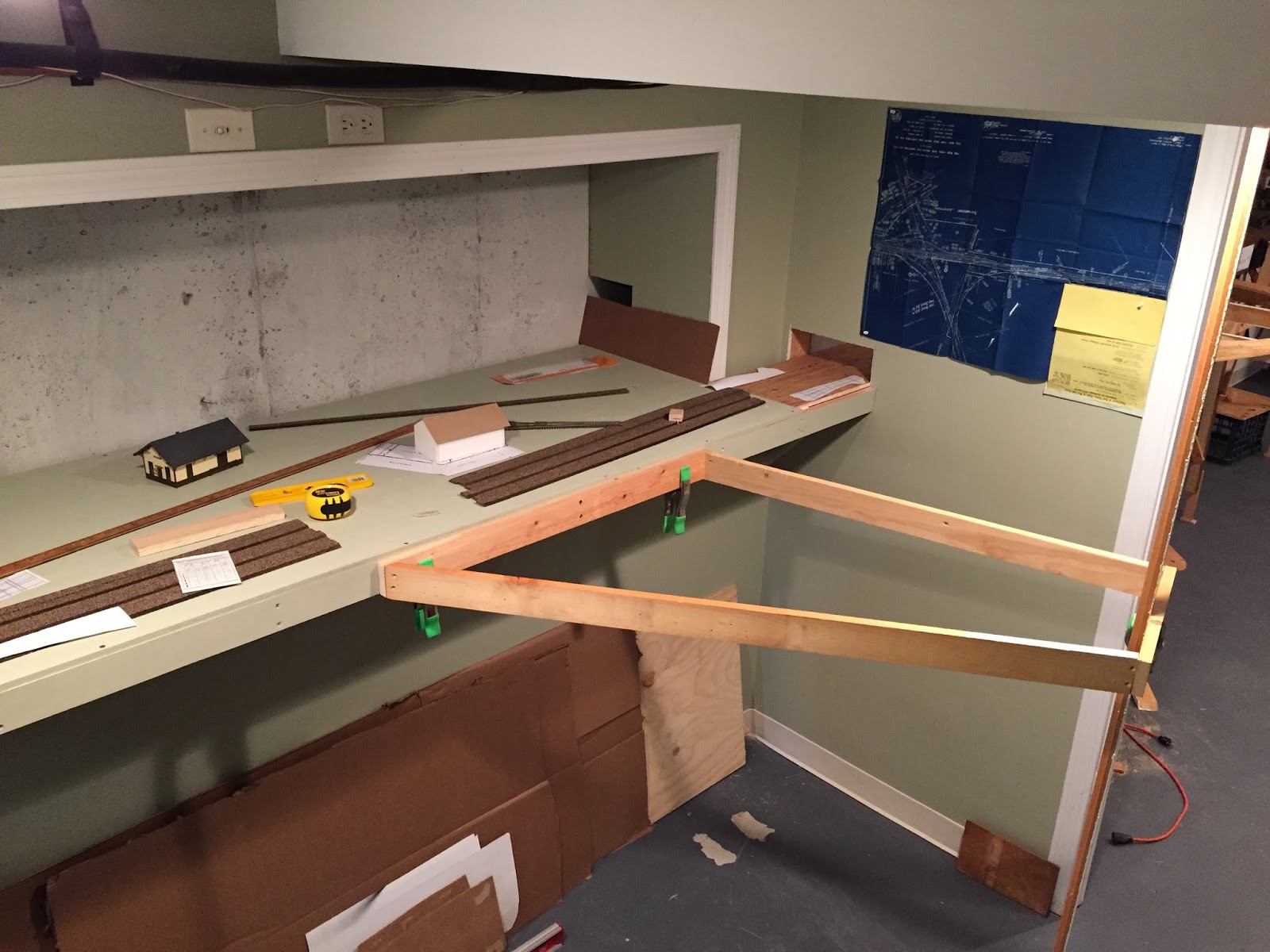
After all this though, I couldn't resist putting some real, actual track on the wye benchwork. Before finalizing the position of that benchwork section, I just wanted to confirm that the track could go where planned. Thankfully, it does. Whew!

Bonus: I can really start to see this area coming together - sure adds a great jolt of motivation to keep going!

Saturday, June 20, 2015

Happy Father's Day!

(I originally posted this back on April 23, but thought it'd be fun to repost it, considering the holiday & all. Hope you're able to spend some time with your dad workin; on the railroad - and if he's no longer around, run a train in his honor.)

I'm blessed in many ways that I won't recount here, but one of the best blessings is still having my folks around. They recently retired to Tennessee so when they get the chance to come back to CT to visit, it's especially nice. Strangely though, never before had my dad joined me in an operating session. Until this first after-retirement visit...

But first, a little backstory...

If you've ever checked out the website (as opposed to coming directly to this blog), and have seen the "About" page, you know a bit of this already. I got my start in model railroading when my little brother got a train set one Christmas. Long story short, he wasn't all that interested in the train, but I was - and adopted the set as my own. And with my Dad's help, we dove head-first into the hobby, buying plywood and lots (and lots!) of Atlas Snap Track. Dad didn't need another hobby and eventually bowed out as my interest continued to grow - but he's always been interested in the different layout projects I have had over the years (including a trip to Vermont to salvage a large layout from an old friend).

It hasn't been until recently, though, that I've actually had something to operate - largely due to a rebuilding of that VT layout into two modules. And now that I've had a few ops sessions on the Valley Line proper, it was way past time to ask Dad if he wanted to try his hand at the throttle. The pics tell the story, but I think he had a good time - I know I did!

All smiles at the start of the session in Somerset. I figured we'd start with the finished portion of the layout. Even if you're not a die-hard ops guy, you can still appreciate the structures and scenery. Bonus: all of this came from the VT layout we salvaged together many years ago.

Even though this was his first session, the look will be familiar to anyone who's been at an ops session. You're always wondering just how to get the cars to where they need to go.

After fun in Somerset, it was off to Mill Hollow - another module made up of savaged structures from the VT layout.

Since I'd started him on the Air Line Local, Dad had to get to Middletown to drop off & pick up cars.

Once he was finished with the Air Line Local, I asked if he wanted to try his hand at the Valley Local next, to get use of the whole layout. It's not as pretty to look at, but the run is longer so you can really enjoy seeing the train go by. Or, as in this case, part of the train: He was so focused on the engine here at Rocky Hill, and I was so focused on getting the photo that we both failed to notice that 1/2 the train was still back in Dividend(!) Oooops

After picking up the rest of the train, we finally made it to Wethersfield where Dad did some final switching before tying up for the night. The train couldn't get all the way back to Hartford since I'm trying to redo the backdrop at the north end of Wethersfield (you can make out the temporary vinyl in the background) and it's blocking the track.
Despite the minor snafus, we had a fun couple of hours just switching cars around on a couple of low key locals. It was a far cry from the slotcar-like running we used to do on the old 4x8s, but after over 30(?!) years' time, it was just as fun. And, best of all, we still got to do it together. And that's what I'm thankful for most of all.

Tuesday, June 16, 2015

Fun With Stools & Clamps: The Wye Gets Started (again)

And.... we're off!

I'm back to the basement after a long-work-and-short-vacation-induced hiatus. I was a bit surprised at how difficult it was to get back down there, despite chomping at the bit to make some more progress. But "thinking dreaming about" and "actually doing" can apparently be two very different things. Thankfully though, once I got started I got back in the mood quickly.

At first I thought I'd install the backdrop behind Saybrook. The basement/foundation wall there is pretty unsightly and some masonite would cover it up nicely. But it quickly occurred to me that I should at least get some of the track down there first - otherwise I'd have to try and do the trackwork through the "tunnel" holes. So I turned my attention back to the Saybrook Wye.

I'd last worked on this with Pieter way back on April 23 (click here for the details) and here's where we'd ended up:

After much figuring and calculating, we'd come up with what you see above - but it was just temporarily mocked up since I still had to get a treadmill out of the module room and it'd be much easier to do that without this section of benchwork in the way. I got the treadmill out sometime in May, but whatever basement time I had I used to construct the staging yard benchwork & subroadbed. Now that that's in a good state & ready for track, it was high time to continue the benchwork from Saybrook "north."

My first step was to figure, again, exactly where the wye benchwork needed to go. In my haste to get the mockup out of the way, stupid me didn't think to mark where it had been. All I had to go on was a little "X" chalked in on the floor. Fortunately, that was all I ended up needing.


Above is "Mockup, ver. 2"  It was a bit more difficult without Pieter there to help me, but as you can see, I'm pretty resourceful. Nothing a bunch of clamps and a stack of stools can't accomplish! I wanted to maintain a 2' minimum aisle, so you see that from the corner of the bottom step to the face of the benchwork (marked out with a 4' level turned vertical). And you can barely make out the homemade plumb bob on the left, with the string held in place by my hammer.


Here's a close-up of the plumb bob: "X" marks the spot!

I could have done the "normal" thing and - once having thoroughly marked where the benchwork's supposed to go - taken the frame back to the shop and added the cross-pieces. But what fun would that be? Especially when you can build it in place using a fun clamp?


I got out my $12 framing clamp (I'll say it again - it's one of the best $12 you'll spend) and clamped a crosspiece in place to hold it for drilling/screwing in. In the pic above, it's holding a 90 degree angle. Pretty straightforward.


But here is where the clamp really shines - here it is holding the other end of the crosspiece at a 22.635 (or thereabouts) degree angle. I'd marked the angle cut on the crosspiece beforehand and used my miter saw to make the cut. Having this clamp hold things together for drilling/screwing was a huge help.


Not the best overall pic of the result, but here's the wye benchwork all done and ready for legs. Well, actually one leg - to replace that stack of stools(!). With a bit of angle bracing, one leg should be sufficient, then it's just a matter of attaching this section to the existing benchwork.

Next step will be to either A) mockup the subroadbed that will go here (the "north" leg turnout will be at about the end of the benchwork), or B) start making the liftout section that will go between this wye benchwork and the wall. In order to get to Essex, the mainline will have to punch through the wall just to the right of door.

So the final countdown to my open house begins! My goal is to have all the benchwork, subroadbed, and operating track DONE - and I have less than 8 weeks to go . . . Stay tuned for what I hope will be some very regular pics of my progress!

Tuesday, June 9, 2015

Give Me Five Minutes More...

Those of a certain age - or younger folks that enjoy good music - will remember the tune "Give Me Five Minutes More." It's not only a great song, but it's a good mantra for making progress on your layout. I've written before (herehere & here) about how effective it is to take advantage of little bits of time to get something - anything - done on the layout, no matter how small or insignificant. Those little bits of time add up - sometimes even more so than than the much more elusive large chunks of time.

And doing those little bits has a way of warding off frustration too.  Case in point:

My busy time of year at work is finally over, but basement time is still hard to come by. Too many things got deferred while I was working late hours, and this week and next week will be busy with a 20th anniversary, a long weekend trip away, and parents visiting from way down south. All good things, to be sure, but not compatible with lots of time on the layout.

So last night I figured I'd head downstairs "for just 5 minutes or so" to see what I could accomplish. Here's what I saw...

Remnants of winter training - the physical kind, rather than the railroad kind - needed to be picked up and stored away.

The under-the-staging-yard area had become a dumping ground of miscellany - especially bad since the cardboard boxes tend to soak up any basement weeping that occasionally happens in that corner.

More winter training remnants - this shelf held my iPad for watching TrainMastersTV during workouts
The  workout/training stuff had been taking up the space that I plan for Essex/Deep River and since winter is over (yay!) and benchwork for this area is on the horizon (double yay!!), it was time for it to go. The treadmill had already been moved to the other room - I had only to put away the bike trainer and clean up.

It's already looking better! Those L-girders on the wall will support East Haddam, eventually.
All that detritus under the staging yard was really starting to get in the way and when I run the outside spigot/sprinkler, I sometimes get water in this corner. So I hunkered down and got that stuff moved out too...

Much nicer and makes it much easier to move around under there.
Finally, down came the shelf - and the rest of the wall hangings won't be too far behind since I need to paint this wall sky blue as the first step in a backdrop for East Haddam...

The turnback curve between East Haddam and Deep River will be there in the corner.
It turned out that "5 minutes" ended up being closer to 45 minutes by the time I got these little chores done, but the time spent was WAY better than the alternative - sitting in front of the TV, or worse. And I'm just that little bit closer to getting benchwork installed in the area - and consequently just that little bit further along on the layout.

So, whatever you do, don't make the mistake of thinking you don't have enough time for your layout. True, you may not have the luxury of hours at a time, but even few minutes can make a huge difference if you put enough of them together.