Friday, July 31, 2015

Fun Stuff Friday - Ballasting

I know, I know, you don't usually associate ballasting with "fun," do you?

Well, you're clearly doing it wrong!

Check out the video below for proof:


Having trouble spreading and tamping the ballast on your model railroad? Tiny rocks getting everywhere, except where you want them? Lots of itsy bits left on top of the ties? Try using an orbital sander to vibrate those little grains and nestle them snugly in-between the ties, where they belong!

And, just for the record, no - I would not recommend that you apply the sander directly to the rails. . .

Thursday, July 30, 2015

Marathon Work Session - 7/16/2015

I was posting pretty regularly (like, Every. Single. Day.(!)) leading up to my going away on vacation, but said vacation meant no layout work. So, knowing this would be the case - and all-too-aware that my deadline was looming - I bribed persuaded the guys to come over for One Last Big Work Session.

To my very pleasant surprise, just about every one of our merry band of men were able to make it - 8(!) guys in all. It was a ton of fun and a lot of help - my biggest challenge was trying to keep them all supplied and busy!

Here are some photos from what turned out to be a record evening . . .

The aforementioned "bribery" - still cheap labor no matter how much pizza you buy... Left to Right: Randy, Joseph, Roman, Dick, Pete, Pieter, Tom, Bill

Here's (most of) the "electrical crew" - Pieter and Dick soldering little wires on toggles for switch machine controls; Tom continuing the busway bus line down to Essex.

The other half of the electrical crew - Roman & Joseph wiring feeders under the staging yard.

Scenery crew - Pete and Bill working in Dividend & Rocky Hill, respectively (though not particularly respectfully :^)

Quality Control Expert Randy checking out the wiring on the mainline heading to staging - he also laid most of the Shoreline, with help from Joseph and Roman.

Believe it or not, Pieter was actually not feeling all that well - but apparently we were able to help, if even only for a little while. Of course, his latest creation may have had something to do with his maniacal laughter good humor . . .

Invasion of the Toggles!!
This is clearly the product of a (OTC) drug-addled mind.
I'm glad The Missus encouraged me to take photos - which I would have totally forgotten in all my running around getting stuff for folks and answering questions. On one of my many trips upstairs, she stopped me to say how remarkable it was that so many of the guys had taken time out of their schedules to come pitch in and make some more progress on the layout. And I couldn't have agreed more - I'm truly a blessed man.

So thank you again to Bill, Randy, Roman, Pete, Pieter, Joseph, Tom, and Dick (we really need a Harry to join us) - you've each put your unique mark on my layout and it's become what I hoped it would - a tangible reflection of the many-varied talents and abilities of a great group of guys.

Tuesday, July 28, 2015

Another Saybrook Structure Photo (re)Discovered!

This is a lesson in making sure you review what you already have before you go too far doing new research...

I've been trying to figure out what colors to paint New Haven Railroad related structures, c. 1947 (click here and here for the discussion so far, and don't forget to check out the comments).

The biggest challenge, of course, is finding color photos from the era.  This one. . .


. . . from the spring of 1949 (according to the photographer, John Wallace) shows the Old Saybrook station and freight house in a monotone "all brown" color. While we don't need to go into actual colors here (since I did so here), this photo is helpful for establishing a point in time by which the freight house, for example, had been repainted from an earlier "two-tone" scheme.

That two-tone scheme had definitely been in use as late as the early 1940s, at least in Old Saybrook, as in this photo:


"Early 1940s" to spring of 1949 is still a pretty large window for speculating when the color scheme changed from two-tone to monotone. But looking at (for what has to be the millionth time) Shoreliner Vol. 22 #4 again (the one with John's Valley Line article), I see the following on page 10:


In case you can't read the caption, this is a shot of the Old Saybrook freight house in December 1946.

Dec. '46 to early spring '49 is a MUCH narrower window - heh, but it still doesn't solve my problem. I still don't know precisely how the structures were painted in October, 1947 (my chosen modeling period).

But does it really matter? Or is this actually a - dare I say it? - opportunity (especially given my recent era creep)? If I want to depict October, 1947, there's nothing to say that either the two-tone or monotone scheme wouldn't be ok. I just know I can't depict October 1946 with a monotone building or October 1949 with a two-tone building. (btw, it's always October on my layout - it's much easier to change locomotives and cars than it is to change scenery...)

Of course, we're just talking about the Saybrook freight house - other structures kept the two-tone scheme MUCH longer. See this photo of Wethersfield station from the summer of 1951:

Also from Shoreliner Vol. 22, #4
Of course, all this is assuming the captions on these photos are correct. I haven't independently verified them yet. But they were published in the Shoreliner so they have to be correct, right? :^)

Monday, July 20, 2015

Great Idea (not!)

So, I thought it would be bright idea to cut my gaps in the curves on both ends of the dog bone in order to isolate the reversing section and make it as long as possible. 

I just succeeded in ruining that curve and will have to redo it. Turns out cutting gaps on curves will introduce a kink in the curve.


So much for soldering the track to make it flow smoothly.

Don't make this mistake - learn from my stupidity. >:^)

Sunday, July 19, 2015

New Haven Railroad Structure Paints for the 1940s

While researching NHRR structure paint schemes is fun, sometimes the work is done for you. In the case of the Old Saybrook Tower kit, you're told right in the instructions what to paint it:
"The older paint scheme of the tower was a tan with brown trim . . . [t]his color was confirmed during a visit to the tower . . . [p]eeking inside, we found the inside of the stairway to be painted with the tan color."
They suggested using a 60:40 mix of Floquil Flesh and Foundation for the tan color ("cut with just a little bit of white") and Floquil Rail Brown for the brown trim color (lightened with a little white). Since I'm not sure how that will actually look compared to the color photos I've discovered (and also because I haven't yet found a bottle of Floquil Flesh), I'm going to wait until I can make a color swatch as a test before painting the model.

Alternatively, I could follow what BillC used for his model of the Canaan, CT station - PollyScale Rust. He used that for the walls & trim, painting the window sashes white.

But what about the most popular NHRR structure paint combo - the two-tone color scheme which was in use "from sometime between the onset of the Depression and the end of WWII?" Even in my late '40s era, some buildings were still in this paint (e.g. Wethersfield, Essex, and Deep River stations) and this scheme was replicated very nicely by JoeS on his model of Cornwall Bridge station. See below:

Joe's model - a photo of which I reluctantly include here since it far outshines any of my modest efforts!
He used Testors Model Masters paint - Military Brown # FS 30117(F) for the trim (darker color) and Radome Tan # FS 33613(F) for the lighter tan color of the walls.

On the other hand, our good friend, the late John Pryke used Floquil Depot Buff and Roof Brown to achieve a similar effect, according to an article in the November 2009 issue of Model Railroader:


While the New Haven certainly painted its structures in colors other than what I've described here (i.e. red with white trim starting in the 1950s), these paints should give you some pretty good options for what NHRR buildings typically looked like during the 1940s.

Of course, the best guidance I can give beyond what's here is to find photos of the particular structure you're modeling, preferably from your chosen era. Those photos, by far, would be your best reference. But as you can tell from my saga of Saybrook tower, such resources aren't that easy to come by. The colors suggested here will at least get you started.

Saturday, July 18, 2015

Lighting the Saybrook Scene


Here's the Saybrook scene with the backdrop in place and (almost) ready to paint. As you can see, it's pretty dark, and before I do my last coat of topping and start painting, I really want to be able to see what I'm doing. So it's time to Install Lighting.

Now, lighting is one of those areas where my reach sometimes exceeds my grasp. In my mind's eye, I see the Saybrook scene lit like a museum diorama - all indirect/spot/track lighting, hidden from view, lighting only the scene. But this is an expensive enough hobby as it is and I'd rather focus my limited resources on more railroady stuff than professional quality lighting. IMHO, this is an area where one can afford to economize. Here's how I do it:


Shop Lights - $10.97 each and bulbs $4/pr at WalMart - though I have to admit, noticing the reviews while preparing this post, I'm wondering how wise this choice will end up being. All I can say is that I've used these over my older section of railroad for 2 1/2 years now without a problem.

If you have an unfinished basement ceiling (first of all - why?? At least cover your ceiling joists with plastic to keep dirt & dust from raining down), you can just attach the lights to the ceiling joists. But if, like me, you have a drywall finished ceiling, what do you do? Well, you can use a stud finder to "see" where the joists are and screw your mounting hardware into them. Or.... you can do what I do. . .


. . . use a combination of drywall anchors and screw hooks. This way you can locate your shop lights anywhere you want, without restriction. And installation couldn't be easier...

Locate where you want the first light chain to go (place the light where you want and mark where the chain will hit the ceiling), drill a 1/4" hole, push & screw the achor in. Note: if you hit a stud when you drill, you won't need the anchor (though you may need topping to fill the hole around the hook)

Screw in your hook and hook on your light chain, adjusting for height.
Now your layout area probably looks like, well, a shop. But this next little innovation transforms the "shop look" into a "museum look." Well, to my mind anyway...

Get yourself a couple of small binder clips and some picture hangar wire. Attach the wire to the clip as above.

Clip to the front (layout) side of the light, in line with the chain - and then attach the other end of the wire to the hook, pulling up the layout side of the light.

Voila!! Instant faux valence! The light is directed away from the viewers and the aisle and directed instead toward the layout.
This isn't a perfect lighting solution, but it's certainly inexpensive. And, with a little adjustment, can be make to look almost as effective as a full lighting valence, with a fraction of the time and expense.

Even though it's not totally necessary (I'm already getting 90% of the desired effect), I'll likely add a valence anyway, if only to hide the shop lights and wires from view. I'm debating using some of that vinyl flooring I have left over (much easier on foreheads) - otherwise, I'll go with a more traditional masonite valence. Thankfully, given how well this scene is now lit, there's no hurry to decide.

Friday, July 17, 2015

Vinyl Backdrop

I started the Saybrook backdrop a few weeks ago but I'd only gone to the edge of the proscenium with masonite since I wouldn't be able to curve it as tight as I needed to. Following a tip from Joe Fugate, I used some scrap vinyl flooring material to extend my backdrop around the tight curves at the "west" (right) end of the Saybrook scene. You can follow my process through the photos below...

Add caption
You can see here that I've used fiberglass mesh tape to cover the joint between the two sections of masonite. I'll go over this with vinyl spackle, which is a bit more flexible than traditional drywall topping. The vinyl flooring is on the right - backside out. I've glued the left edge to the masonite with regular vinyl flooring adhesive caulk and held it up with my 2' level leaning against it.

And here it is with the mesh tape added.
  

Once I knew the left edge was secure, I spread more adhesive directly onto the wall and rolled it out to be sure it spread evenly.

Pro Tip: In a situation like this, consider a backerboard rather than applying the vinyl directly to the wall. As you can see, having the vinyl go around the moulding and dip back to the wall creates some unfortunate shadows. The 1" gain of space there isn't worth the shadows, IMO. Note also how I cut it to go into the "tunnel." That's as simple as wrapping a present - just mark your cut and cut with regular scissors.

I also put adhesive on the other wall and applied mesh tape to the right edge of the vinyl to help it feather into the wall. After this, it's just a matter of adding coats of vinyl spackle - sanding in between coats and feathering everything in - and we'll be ready to paint!


Next time you're planning a backdrop, you may want to consider adding some vinyl. Not only does it go around tighter corners much more easily than masonite, but that flexibility makes it ideal for coving corners.

That said, I wouldn't recommend using vinyl exclusively since it's way too flexible for general use, IMO. If you plan to paint it at all after installation, you'll find that you'll need to have it sufficiently supported - and that's a lot of extra work, considering that masonite is to a great extent self-supporting.

But it's another alternative to add to your backdrop options. In the right spot, vinyl is the perfect fit.

Thursday, July 16, 2015

Tracklaying Tips

I've been doing a lot of trackwork lately and thought it'd be nice to share a few tips on how I go about it. Nothing innovative here, but if you're like me, seeing a "normal" (relatively) person do it makes the process more accessible. You see it really is that easy - and hopefully you'll be encouraged to give it a go yourself. So follow along in the pics - and if you have any additional tips/suggestions of your own that you've found helpful, I hope you'll share them with us in the comments!


The Saybrook wye is a good place to start. In the photo above, I've already drawn the center line for the west leg - it's at my minimum radius to stay as tight to the wall as possible. I also drew a straight line (tangent) for where the turnout will go. Along that tangent, I put nails to hold a strip of masonite, as you see here. This is the first step in the "bent stick" method of laying out curves with easements (which are MUCH more graceful, realistic, and make for smoother operations).


With the nails holding it in place, I bend the masonite to the track I want to join to, as in the photo above.


You can put some nails in at the the other end to hold it if you want, but I just held the masonite in place with one hand while drawing a line along it with the other. You can see the result above - very nice, graceful, prototypical-looking lines.


An alternative to using nails to hold the masonite on a tangent - especially useful for loooong tangents - is to clamp the masonite to a straight edge. A level is ideal for this, as in the photo above. Bonus: you can easily move this assembly side-to-side to get the line exactly where you want it.


Here is where all the staging tracks go straight. I've drawn the tangents in first and need to connect the lines back to where the turnouts are in the yard throat. Again, to get a smooth line, I'll use the masonite strip.


Now, that doesn't look like the smoothest of lines, but note that there will be a turnout where that jog is.

And here are all the staging track center lines drawn in. My only regret is that I didn't start at the back (far right) and work my way forward (left). That last line on the right is the most graceful and good-looking, and while all the lines are nice and smooth (guaranteed by the masonite), it would have been even better to have them all parallel that line on the right. If this weren't staging, I'd probably redraw the lines for aesthetic reasons - but no need to here.


With all the lines drawn in beforehand, Roman could just come in and start laying roadbed and track according to the lines.


At least it looks like he's having a good time - must be cuz all the figuring was already done...


And you can see the result of all that work above (thanks Roman!).

If you haven't tried the "bent stick" method of laying out your curves, I highly recommend it. As you can see, it's super easy and I think you'll be happy with how it turns out.

Tuesday, July 14, 2015

Tuesday Tips: MicroMark's Switchtender Switch Machine

I'm considering using switch machines for the turnouts in the Saybrook scene. Thing is, I haven't used or installed a switch machine since I used Atlas Snap-Track back in the early '80s. And "install" is overstating it with those things. So I'm pretty intimidated by the prospect of powering my points.

Thankfully, PeteL had on-hand a spare of the machine he uses: The SwitchTender from Micro-Mark. And, even better, he agreed to bring it over for me to try.

It installed so fast, I forgot to take many pictures along the way, so this is from Micro-Mark's website.
I approached this install fully expecting to spend the whole afternoon, taking my time to be careful. Consequently, I was very skeptical about the "Installs in under 5 minutes!" claim. But I have to say, while it did take me longer than 5 minutes, I really can't imagine the install being any easier than it was.

I won't go into a play-by-play of the install, but the basic steps are:

  1. Locate the center of where your throwbar hole will be;
  2. Drill a hole for the actuating rod (which will thread up through the throwbar hole);
  3. Install machine bracket;
  4. Form actuating rod;
  5. Install machine in bracket, threading actuating rod up through throwbar hole;
  6. Adjust & tighten;
  7. Trim rod.

Things went very well according to the instructions (which you can view here for more details). Since my turnout had not yet been installed, things were especially easy. The instructions for installing the machine on an in-place turnout are understandably more involved.

That all being said, I quickly discovered (and Pete filled me in on) a couple of tips that the instructions don't mention, but which I think you'll find helpful. I sure did.

Tip #1 Unless you're afraid of scenery material falling down through the hole, drill a 1/4" hole for the actuating rod rather than the 2-1/8"-holes-side-by-side-and-1/16"-apart that the instructions call for. They intend for you to make a little slot for the rod to move in, but it's a very fussy process and would likely be fussy in operation. Best, in my mind, to provide lots of clearance, and more easily.

Tip #2 If you're using Micro-Engineering turnouts, you should remove the little point locking spring since the machine isn't quite powerful enough to move the points against that spring. Besides, you want the points to move smoothly - not snap over.

Tip #2a Speaking of ME turnouts: the supplied actuating rod (for newly installed turnouts) is .046" copper wire. The holes in the ME turnout throwbar are a bit smaller (.035"), so I used a small (#56) drill bit in a pin vise to ream out the throwbar hole. Incidentally, while ME turnouts have 3 throwbar holes, I opted to use the center one.

Tip #3 No matter how tight you think you tightened the bracket mounting screw, the machine will likely work the bracket loose over time. So Pete suggested installing two "stop screws" at the back of the bracket, like this:

Two little wood screws, set behind the machine mounting bracket, to prevent it ever twisting or turning.
Tip #4 Use a 7/16" wrench to tighten the bracket around the machine. The instructions don't mention needing this tool, but you won't be able to get the bracket nut tight enough with just your fingers.

Below is another picture of my install, with the resister wire-nutted to one of the motor leads:


I tested the machine by hooking up a pair of temporary wires from the motor lead & resistor to an old 12v power pack. Worked like a charm. To move the points the other direction, I just switched the wires. Of course, that's just for testing. For a permanent install, you'll want to use a DPDT toggle switch to reverse the polarity - or the Micro-Mark-recommended 3PDT switch (if you plan to power the frog).


The last step, once I was satisfied everything was well-adjusted and working properly, was to cut off the excess actuating rod. As you can see (or not), it's barely noticeable.

All in all, I'm very happy with the machine and how easy it was to install. While it did take me longer than 5 minutes, I can certainly see me getting to sub 5-minute installs after another install or two. The SwitchTender is also economical: $15.95 for a single, down to under $12 each for 100 or more. Check the website for quantity discounts at other levels.

Even at those prices, powering turnouts isn't an inexpensive proposition no matter how you cut it, and I don't even have that many to do (the rest of the layout outside Saybrook will be all manual turnouts). And remember you'll also need to buy a power supply, toggle switches, and wire.

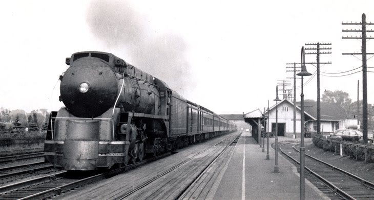
But the idea of having at least my mainline turnouts powered in Old Saybrook is VERY attractive. I've been researching the Saybrook tower (here and here) and it would be awesome to be able to have a "Tower Operator" position during operating sessions. I just don't know whether that'll work logistically - Is there any limit to the distance the toggle switch can be from the switch machine it controls? I'm considering having all the Saybrook turnouts operated by toggles on a control panel above what could be a "towerman's" desk - which is about 10-15' away.

It's certainly an intriguing idea, but first I need to decide whether to go to the expense of all those machines. At least in the case of the SwitchTender, I won't have to worry too much about the installation.

Monday, July 13, 2015

Rocky Hill Scenery Started

Sunday work sessions are whirlwind 4-hr affairs, tucked in between brunch & dinner. Bill and Pete made it over to continue the scenery in Rocky Hill that they started last week and I tried to keep them supplied with all the necessary resources, from materials to tools to the-all-important-snacks. As you'll see in the photos, we got a lot done!

Pete's in Dividend staying ahead of Bill, who's adding more to the area just "north" of Rocky Hill.
 

Early on, they determined that it'd be a good idea to put the stone foundation for the Rocky Hill station in place and scenic around it. This, despite the fact that the station isn't built yet - there's just a mockup structure. Since it's so critical that the foundation footprint be spot-on, I decided to confirm that the mockup's footprint was accurate. Good thing I did. It wasn't. Even worse - I can't determine the actual footprint size from the Sanborn map.

If ANYbody has any information on the footprint dimensions of the Rocky Hill station and the freight house (or miracle of miracles - if you actually know where I can get plans!), please let me know. In the meantime, we're estimating the footprints based on the Wethersfield freighthouse/station kit.

BTW, the station footprint is sketched in in the photo above, and I hot glued some foam core to start the platform area.

Thankfully, my false start and insufficient research didn't diminish the progress Pete & Bill were making. And the proof is in the pics . . .


They tell me that "there's still more to add" but it sure looks pretty close to finished to me! I still need to figure out what - if anything at this point - I'm going to do for a background here. Nothing's really needed to be on the backdrop though, which is why I chose to start the scenery in this area.


It's starting to look pretty good! I'm glad I had a good scenery stash on-hand, but this process sure eats up lots of material. The results are worth it though - especially the first time you see a scale model in a scene you'd only ever seen in your mind.