Thursday, July 28, 2016

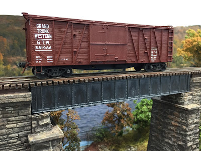
Grand Trunk Western #581986 1-1/2 Door Boxcar

So now that it's done, I figured this would be a great time for a recap and to get all the pics and information together in one place (click here and here for previous posts on this build).

As you may recall (or not, if you're new to this here blog...), I got started on this project at a "hands-on" clinic at this year's NERPM. Don Valentine graciously provided an Accurail single-sheathed boxcar kit (model 4000/4200) and some extra parts (Standard Car Co. #1000) to convert the kit into a door-and-a-half boxcar.


Along with the kit and parts, Don also supplemented the conversion kit instructions with a multipage document which included a description of the prototype, a diagram, and some photos. The parts instructions also mentioned Richard Hendrickson's article on these cars in the April, 1993 issue of Railmodel Journal:


The full article can be accessed here.
And I came across this list of additional prototype information:
GTW 583699, MM 12/87 pp 72-75 (article includes drawings), RMJ 2/01 pp 50-56
GTW 584618, RMJ 11/00 p18, 2/01 pp 50-56
GTW 583298, Hendrickson, "Focus on Freight Cars vol. 1", p 24 
but I'll be dipped if I can remember where I got it. If you recognize this list, please let me know so I can provide proper attribution.

The build was very straight-forward: just follow the instructions carefully. As you can see in the first pic above, I was able to get the door positioned and glued on very quickly - during the clinic AAMOF. Drilling the holes for the remaining details was a different story however...

I use a sharp pin to make a starter dimple for drilling the hole.

The instructions for the conversion parts provide a couple of handy-dandy drilling templates which you cut out for positioning the holes (see above, and below)...


But BEWARE! Make sure that you cut out the template to the correct size so that the hole is located, um, correctly.

As you can see above, I inexplicably cut off the pointy tip of this template. And you may recall from a previous photo that I snugged it up to the top - as I thought I needed to. However, that resulted in a door cleat location that was MUCH too high. See below:


Focusing on the two holes on the right: the top one is where I drilled based on the template's first location. If I knew then what I know now about freight car construction (or at least door cleat placement), it would have been obvious to me right away that I was locating the detail too high. The lower hole is better - but it should still have gone lower to match the height of the other cleats. No worries - a little dab of body putty filled in the incorrect hole.

LESSON: Use templates with caution & always go with what you know to be correct despite what the template tells you. Or - rather - just make sure you cut out the template properly(!)

After the "hole drama" there was little else remarkable about the standard build. Here's a photo with all the conversion parts attached to the car:


You can readily see what a difference the parts make to the over all look.

Next step was to secure decals. Don mentioned that Black Cat Publishing had the correct ones, which you can find here.


Just as I was about to start decaling, I got some - er - feedback suggesting that I might want to remove some of the molded-on detail, at least the side grabs.  Well, I did the side grabs...


I actually took down even more material, and re-introduced "grain" lines with the point of an Xacto. But, no, I did not bother with NBW castings.
 ...and the end grabs (not pictured) and the lateral roofwalk corner grabs . . .


Yeah, I got a little carried away with my favorite chisel (which I highly recommend, btw), but the result was definitely worth it:


As you can see, in addition to adding separate wire grabs, I added A-line stirrup sill steps (sorry Ted), scratchbuilt a couple of uncoupling bars, and added KD airhoses. After all that was done, the car was finally, really ready for the paint shop.

Since there are usually long spells between my painting freight cars, I "get back into it" by starting with the underbody and trucks since they're pretty hard to mess up. So my airbrush and I got reacquainted and I shot the sideframes first with some grimy black (being careful to mask the bearing holes). Then I used a microbrush to apply my mixture of grimy black paint and baking soda to the wheel faces. I think this really does a great job of simulating the caked-on oil, grease and dirt so common to steam era freight car wheels. It's hard to see, but *I* know it's there and it makes me strangely happy. Click on the image for a closer view:


I sprayed the rest of the underbody with the grimy black and then tackled the carbody with a rattle can of Tamiya Fine Surface Primer. It ain't cheap, but it's really good and easy to use. (btw, I did the painting after cleaning all the parts and carbody using a toothbrush and denatured alcohol).

The carbody itself was a little more challenging. Don suggested using AccuPaint AP-54 "Rich Oxide Brown" as a good color for CN cars (and appropriate for GTW cars as well), but I had TruColor oxide brown on-hand, and I plan eventually to weather the car moderately to heavily, so I went with that.

Only problem was, my paint had gelled in the bottle. I'd heard you could thin it with acetone, which is what I did - at a 2:1 ratio(!). At least it went through the airbrush without clogging - but the bad news was 1) it took MANY coats to get enough coverage from such highly-thinned paint, and 2) using the acetone made the finish flat rather than glossy.

Fortunately, before I dove into decaling, Bill saw the carbody and said he could tell I used gray primer. Apparently, the body still wasn't adequately covered - and I hadn't noticed since it looked So Much Better than before. So we shot it a couple more times with less-thinned paint and let it dry for a bunch of days.

Next step was to apply my cool new Black Cat decals. Now, my process for decaling earlier cars - which also had a very flat finish - was to apply Future floor polish to the model, place the decal on that, and let it dry. I'd then add decal setting solution on top of that. That process worked ok, but for some reason it resulted in some white residue which I had to deal with. Not a big deal, but a little annoying.

This time, I decided to go with a more tried-and-true method:

  1. If the model isn't already glossy, spray on a gloss coat. I used Testor's gloss coat from a rattle can, but you could also use an airbrush. I thought the rattle can was fine for this. Let dry thoroughly.
  2. Cut out the decal leaving as little decal film around it as possible and place in distilled water.
  3. Apply MicroSet to the area where the decal will be applied.
  4. Remove the decal from the water and "float" onto the setting solution. Use a toothpick or something else that's not sharp to position.
  5. Wick away any excess fluid with the corner of a paper towel, or a makeup sponge. Let dry.
  6. If there's any "silvering" (evidence that there's air trapped behind the decal), prick the areas and add MicroSol and let dry. If that doesn't cause the decal to really settle down into any nooks/crannies (or - in the case of a wood-sided car, between the boards) just add additional applications of MicroSol until it does.

It took a few applications and since I was doing each side & end separately, the whole decaling/setting process took a few evenings, but the result was worth it:

One side done - three more to go.
A note about decal placement on this particular model. I followed the diagram included with the decals. Mostly. Which is to say, the left end of the car followed the diagram precisely; but on the right end the decal wouldn't fit between the rib and the ladder, so I moved it one panel to the left. I've seen prototype pictures that show the dimensional data on the panel I chose, but those cars also tended to have the weight data (the data on the left side of the doors) one panel to the right of where the decal diagram puts it. So, in the spirit of full disclosure, the lettering on my car is a hybrid at worst.

Of course, if I'd removed the cast-on ladders and substituted grabs instead (as the GTW did (parent CNR used ladders)), the decal probably would have fit. If this were a contest car - and/or if I wanted to spend more time on it - I would have gone to that trouble. And I would have done the underbody piping too (which I skipped since the silhouette created by the frame's center beam makes its absence less apparent).

But for a work-a-day boxcar (and, based on my last ops session, I Need More Boxcars), it's perfectly fine. It has enough stand-alone details added so that it fits in with the rest of the fleet - and the price was certainly right (the car/parts were supplied, $8 for decals, and I had the other details on-hand). Looks pretty good, I think, and once it's weathered even the little compromises I made will matter even less. Bottom line: it's done - and has provided the extra added benefit of generating more modeling momentum!


Wednesday, July 27, 2016

Monday, July 18, 2016

A Few Words About Wordless Wednesday #127

Courtesy Max Miller, from the Pratt & Co. museum, Ivoryton, CT, collection of Peter H. Comstock.

In case you didn't recognize this week's Wordless Wednesday, it's the station area at Old Saybrook, looking west from the Rt.1/Boston Post Road overpass. It's one of those "railroady rich" scenes that just begs to be modeled - and, fortunately, I should be able to replicate most of this scene in my model of Old Saybrook. Let's take a tour "into" the photo, from left to right...

The bins and shed in the left foreground are the facilities of "The Chapman Co. Coal - Coke - Oil" (according to the sign on top of the shed, which you can't read here). I suspect that hoppers (and perhaps gondolas too?) were either dumped into chutes that would feed coal to the bottom of the shed - or maybe, during those days of cheap labor - the coal could have been unloaded by shovel & tossed into the top end of the shed. Behind the bins and shed are Chapman's oil storage tanks, and behind that is the railroad's freight house.

The main attraction though is taking place in the center of the photo: gondolas being filled with crates by the Roger Sherman Transfer Co. of East Hartford. The year is 1943 and the crates are filled with Waco CG-4A Army gliders, manufactured by the Gould Aeronautical Division of the Pratt, Read & Company, Inc. at their Deep River, CT plant. They'll be heading overseas soon - by rail - via the New York, New Haven & Hartford Railroad.

"Wordless Wednesday" is a quick & easy way to get a blog post done and share a cool photo - but as much as a picture is worth a thousand words, sometimes often you need at least a few hundred words to describe all the cool stuff going on.

Special thanks to Max Miller for sharing this photo and especially for all the detailed background info that helps make this particular "Wordless Wednesday" so wordy after all.

Monday, July 11, 2016

Modeling Monday: Making Locomotive Passenger Car Buffers

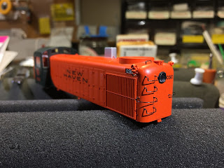
Still working on the P1k RS-2 NHRR DERS-2b (click herehere and here for earlier related posts) and have just about finished adding the body details, so I've turned my attention to the pilot.

Building on their positive experience with dual-mode diesels during the war years (the 60 Alco DL-109s/DER-1s), the New Haven returned to Alco in late 1947 for its first roadswitchers - the RS-2 (class DERS-2b) - and made sure they too were equipped for passenger service. In fact, many of the NH-specific details that have to be added to RS-2 models have to do with adding passenger mode equipment.

But these details aren't limited to just adding a steam generator intake & exhaust stacks. One of the first things you notice about the pilot on the New Haven's version of the RS-2, is the presence of a passenger car diaphragm buffer.


Problem is, there's no detail part for this.

Well, there's this one:

Custom Finishing #306
and it's practically a drop-in for the Atlas RS-1 model. But it doesn't come anywhere close to fitting the Proto 1000 RS-2 model and, as a metal casting, isn't easily modified. So I figured I'd try making one out of styrene that would fit on top of a standard Kadee coupler box.


I started with a strip of .060x.118" for the main part of the buffer and HO scale 1x10 (.011x.112) for the sides. I quickly discovered that .060 wouldn't get me out past the end of the coupler box, so I added a strip of .060x.060 like this:

The buffers are .31" wide to allow the sides to clear the sides of the KD coupler box.
As you can see above, it's easier to use a long strip as a handle, gluing to both buffers at the same time (which I did on a piece of glass to make sure everything was flush). Then trim to fit.


Next, I added the sides as above. In addition to the perfectly-flat surface of the glass, I made sure the side was perfectly vertical by pressing it against a machinist's square as I added Tenax with a microbrush.


The above is the result. Repeat four times.

Once you're done, you have only to sand/file the corners of the main buffer itself and snip/cut the corners off the sides at an angle. This is what you'll have when you're done:


Now, unfortunately, I discovered that the buffer interfered with the coupler once I put it in. Ugh! Fortunately, fixing this was a simple matter of adding a .010" shim between the top of the coupler box and the frame/buffer, as below:


And - bonus! - doing so put the coupler at exactly the correct height (it had been ever-so-slightly high before. Um, about .010" high...)


The coupler still rubs on the buffer a little, but that'll be a simple matter of filing a little material away from the end of the buffer itself.

For an evening's work, I'm pretty pleased with how these scratchbuilt buffers came out, though I'm considering redoing the sides to .020 wide so they'll cover the entire side of the coupler box (and look even more like the prototype - a bit more bulky).

Speaking of the pilot, I plan to replace the molded-on coupler lift bars and grabs with wire. The lift bars are no problem (Detail Associates makes the right bar, but the brackets aren't correct - though I think I can live with that), but who makes these crazy grabs?


They're pretty common on the prototype, and very distinctive with those double bends. But I'll be dipped if I can find anybody that makes them. If you know of a source, please let me know. Otherwise, like the buffers, I may have to figure out how to make them myself.

Friday, July 8, 2016

Accommodating Operators: West End Staging Box/Work Table

One of the many things operating sessions will make apparent is that you can never anticipate all the myriad ways your operators will approach their work. Though I guess I should have anticipated this...

I last covered - literally and figuratively - the West End Staging Yard here (click here, here, and here for the construction process and photos). In case you aren't familiar with the West End Staging Box Yard and don't click on the links, the very short story is that I attached an 8' long 4 track wide staging yard off the front of one of the Air Line modules, as you can see below:

I supported it on L-brackets attached to the module legs, and screwed its back side to the front edge of the module.

Completed staging box/yard

And here it is open
What I didn't anticipate was that my operators would find the "box top" such an ideal workspace. Looking at the photo above, I can certainly see why. Now.

Problem is, that lid is actually pretty heavy and only attached to the side of the staging yard via a piano hinge and some screws - into a 1x3. Yeah, when you put any pressure on this "handy dandy" lid/desktop, the whole thing flexes. I wouldn't want to imagine what would happen if somebody actually leaned on it (as operators may be tempted to do).

So, I figured I had two choices: 1) forbid use of that lid as a desktop (and discourage its use as such by NOT providing any lip at the bottom edge to keep things from rolling/sliding off) - perhaps put it in the Bulletin Order so operators know I Really Mean It; or 2) acknowledge that option "1" is likely unrealistic and embrace the use of the lid as a desktop.

As you might have guessed, I chose option 2 - and it turned out to be a pretty easy fix.


All I ended up doing was adding "support wires" to the top edge of the "wall" of the box, as you see above. Any pressure/pull from using the lid as a workspace will now get transferred not only to the screws (and the all-too-narrow-for-this-application 1x3s), but to the module as well.

Here's a closer view:

The little L brackets were already there as "stops" for the lid to rest on when closed. All I needed was a couple of cuphooks and some picture hanger wire. Drill a couple holes, attach the wire, and screw the hooks down until the wire is nice and tight (and your wall is - and remains - vertical). Just make sure the wire clears your rolling stock, of course.

While using the lid as a desk dramatically cuts down on the space in an already-tight aisle, I figure it'll only be used at the start of the session by 4 guys (two crews) at most: Air Line Local and PDX-1. Actually, only PDX-1 should be necessary at this point since they're the only local in this staging yard at the beginning of the session (The Air Line Local is staged in the corner of the room). But we'll see how it goes. In any event, those 4 guys have no reason to pass each other in that aisle when the box is open.

Now I suppose they're gonna want a lip along the bottom of "their desk" to keep their pencils and paperwork from rolling/sliding off. We'll see about that. While it's important to accommodate your operators, it's also fun every once in a while to remind them who's boss.

But, yeah, I'll probably add that lip at some point. Soon.

Hope you're able to get some modeling done this weekend! I, for one, hope to get further along on my GTW boxcar (glossed it last night so it's ready for decaling) and, hopefully, finish detailing my DERS-2b (RS-2).

Happy Friday!

Wednesday, July 6, 2016

Tuesday, July 5, 2016

Tuesday Tips from the DERS-2b

Just a quick post highlighting a few tips I came up with while detailing my Proto1000 RS-2 New Haven Railroad DERS-2b.

First off - need to bend wire at precisely the right length? Get out your handy-dandy dial caliper (you DO have a dial caliper, don't you?) and do it like this:


I needed to make a bend at exactly .040" - so I set the caliper at .040" and used the internal jaws to make my bend, as you see above.


Here's a closer view, shot with the macro lense app on my phone. As you can see, you set the end of the wire at one side of the jaws and use the other jaw to make your bend.

For my next trick tip, I had a detail I wanted to mount - problem was, the bottom of the detail was flat and the surface I wanted to mount it to was curved. I couldn't stand the likelihood of there being a gap at the bottom of the detail - and since the model is factory painted, I couldn't use gap filling CA or putty very easily.


So I decided to sand the bottom of the detail to conform to the curve of the carbody - as you see above. What you may not notice is that there's plastic wrap between the carbody and the sandpaper to protect the model's finish. And it and the sandpaper are held tightly to the curve. Just move the detail back and forth. Takes some care and patience, but it worked well.

One of the big drawbacks of a Proto1000 model is lack of detail. This wouldn't be quite so bad if the model wasn't already factory painted (much easier to add detail to an undec shell) and I didn't want to strip and repaint. Worse, while there were helpful dimples/locators for the grabs (a mixed blessing, as I'll get to in a future build post), for all your other details you're winging it location-wise.

Extra details placed temporarily for location on a pristine short hood top.
So I was confronted with figuring out a way to mark the model so I'd know where to drill all the holes for the extra details. The solution: masking tape.

Took this photo after drilling and removing the cross-tape.
I used the factory-edge as the straightest part of the tape and eyeballed a centerline, as above.


And to get the fore-aft placement, I used crosspieces of tape lined up with features on the sides of the hood (edge of louver door, end of number board). I just marked and drilled along the edges and in the corners.

Trying to add detail to an already-painted/lettered loco can be pretty intimidating, but I found these tips helped a lot to make sure I was mounting the details evenly and consistently. I hope you find them helpful too.

Monday, July 4, 2016

Modeling Monday - Independence Day

In this hobby, when you're confronted with a seemingly insurmountable obstacle, having a large block of time to just put your head down and plow through it, no matter what happens or how long it takes, is just what's needed. Today was one of those days and detailing my factory-painted Proto1000 RS-2 for a New Haven RR DERS-2b was one of those projects.

Forging new neural pathways and developing new skills and confidence are the inevitable byproduct of a day spent working through the walls that have kept me from moving forward.

My "work"day was spent drilling holes and bending wire. It took a LOOOOOG time, and there were a couple steps back here and there for all the steps forward, but I'm pretty happy with the result so far:


And if anybody tells you that Custom Finishing #205 curved grabs for RS units will drop right in, they won't. And they're straight rather than the correct drop grabs. The Cal-Scale grabs (#190-533) are better, but you still have to form the long curved grabs from scratch. The Cal-Scale "RS Corner Grabs" (#190-529) are too large for where the NBW castings are on this loco.

I plan to do a full build post/article at some point detailing all the right parts needed and some tips/techniques in case you have a P1k RS-2 kicking around that needs some detail. Hopefully you won't need quite the large block of time I needed. Save that for another obstacle you've been putting off and - as Paul Simon said - getcher self free.

What better way to end Independence Day than on that note of freedom

Sunday, July 3, 2016

What's in my Spray Booth


As a variation on "What's On My Workbench," I figured I'd share - or at least memorialize - the fact that - YES! I actually did use my airbrush today. This is officially a Big Deal because I have historically been scared stiff of using an airbrush. I started out well enough - I got my airbrush when I was 16 or 17, painted an undec Atlas S-2 body in New Haven green and orange (green cab, orange hood), and promptly put it away. Where it sat for, oh, about 30 years.

I took it out a few years ago to use it - under my friend Pieter's guidance and direction (he got a kick out of the fact I still had the original Propel can and promotional materials in the box: "Badger - Choice of the '80s!") - and did pretty good. I even "flew solo" a couple other times after that. But along with the distractions of layout construction, &etc I haven't airbrushed in a while. And like most things, if you don't use it you lose it - or at least the confidence you once had (or maybe that's just me).

I used it today though, and All Went Well, mostly. I started with the low-hanging fruit of shooting the underbody of my GTW boxcar with acrylic Grimy Black (figuring even if I screwed up, nobody would see it). Then proceeded to shoot the East Berlin Bridge (I had grimy black left, and it's a bridge so I couldn't really screw that up), then used up the grimy black on the truck sideframes (using a hand-held cardboard to mask the inside of the journal bearing boxes). So far so good . . .

Next I needed to paint the carbody itself - a bit more intimidating. And I decided to use Tru-Color #93 Oxide Brown acetone-based paint. But what I had on-hand had gelled a bit (it's a bit old). So I thinned it about 2:1 with acetone and it sprayed fine. Mostly. A couple times it wouldn't come through the nozzle, so I stopped the nozzle and back-pumped the air into the cup. That always loosened things up enough to cause the paint to flow.

Thinned so much, it took a while to get full, even coverage over the whole car, but at least the brush didn't clog. And, better yet, I'm pleased with the result so far.

As per usual, it took me as long or longer to clean up than it did to paint. I'd done a "quickie" clean (didn't disassemble the airbrush) with Windex after finishing with the acrylic. And I used acetone, then lacquer thinner to fully clean the airbrush after I was all done.

Once I put the brush back together though, I figured I'd shoot one more pass of lacquer thinner through to be extra clean. And the brush started pulsating. Did the same thing with Windex. And with distilled water.

So I'm glad I got these things painted while things were still working- cuz I dunno whether I've somehow messed up the airbrush now or not. Can't imagine that I did, but I know enough to know a pulsating airbrush is Not A Good Thing. If you have any ideas/suggestions for what I should try, please let me know.

In the meantime, at least I've taken another step toward Being Comfortable with airbrushing. Hope this pulsing doesn't kill my mojo.

Hope you're able to get to some RR stuff this weekend - Happy 4th of July!

Saturday, July 2, 2016

On the Valley Line This Morning

Monthly Saybrook Special, northbound at Connally Drive at 10:35 this morning. . .


Click here for a view from almost 30 years ago (and taken from the other side of the street, looking north).